Components, Calibration, Component list – Flowline AX1X Thermo-Flo User Manual
Page 3: Standard configuration
Step Two
COMPONENTS
AT14-1610
1 x FT10-1405
1 x LC10-1002
AT14-1614
1 x FT10-1425
1 x LC10-1052
AT14-3610
1 x FT10-5405
1 x LC10-1002
AT14-3614
1 x FT10-5425
1 x LC10-1052
AG14-1610
1 x GT10-1405
1 x LC10-1002
AG14-1614
1 x GT10-1425
1 x LC10-1052
AG14-3610
1 x GT10-5405
1 x LC10-1002
AG14-3614
1 x GT10-5425
1 x LC10-1052
AT14-1620
1 x FT10-1405
1 x LC10-1001
AT14-1624
1 x FT10-1425
1 x LC10-1051
AT14-3620
1 x FT10-5405
1 x LC10-1001
AT14-3624
1 x FT10-5425
1 x LC10-1051
AG14-1620
1 x GT10-1405
1 x LC10-1001
AG14-1624
1 x GT10-1425
1 x LC10-1051
AG14-3620
1 x GT10-5405
1 x LC10-1001
AG14-3624
1 x GT10-5425
1 x LC10-1051
Component List:
Compact Relay Controller
P/N: LC10-1001, LC10-1051,
LC10-1002 or LC10-1052
Switch-Tek Level Switch
P/N: FT10-1305, FT10-1325,
FT10-5305, FT10-5325,
FT10-1405, FT10-1425,
FT10-5405, FT10-5425
Standard Configuration:
AT14-_6__ and AG14-_6__
AT12-_6__ and AG12-_6__
AT12-1610
1 x FT10-1305
1 x LC10-1002
AT12-1614
1 x FT10-1325
1 x LC10-1052
AT12-3610
1 x FT10-5305
1 x LC10-1002
AT12-3614
1 x FT10-5325
1 x LC10-1052
AG12-1610
1 x GT10-1305
1 x LC10-1002
AG12-1614
1 x GT10-1325
1 x LC10-1052
AG12-3610
1 x GT10-5305
1 x LC10-1002
AG12-3614
1 x GT10-5325
1 x LC10-1052
AT12-1620
1 x FT10-1305
1 x LC10-1001
AT12-1624
1 x FT10-1325
1 x LC10-1051
AT12-3620
1 x FT10-5305
1 x LC10-1001
AT12-3624
1 x FT10-5325
1 x LC10-1051
AG12-1620
1 x GT10-1305
1 x LC10-1001
AG12-1624
1 x GT10-1325
1 x LC10-1051
AG12-3620
1 x GT10-5305
1 x LC10-1001
AG12-3624
1 x GT10-5325
1 x LC10-1051
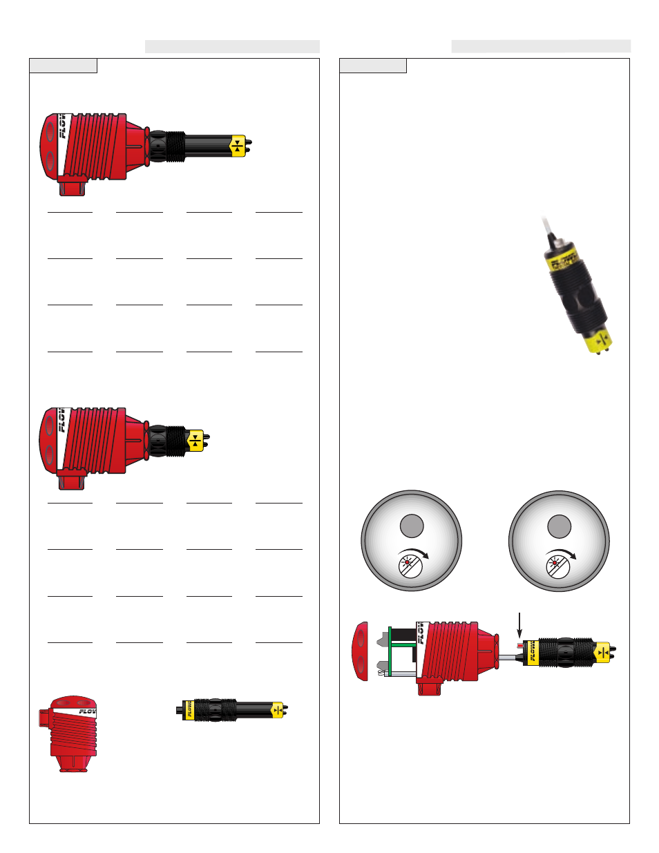
Step Three
Set Points:
If the preset factory calibration is not adequate for
your application, follow the calibration steps listed below. Note: the
switch's internal LED will be on when the switch detects no-flow and
will off when the switch detects flow.
1. Install the fitting and flow switch as described in the Installation
section of this manual. Turn the flow switch and controller power
on and adjust the flow rate to the application setting. If the medi-
um to be sensed is likely to be subject to high temperature varia-
tions, the flow switch should be set at the highest normal temper-
ature likely to be encountered.
2. Locate the potentiometer knob at the top
of the flow switch. The red LED is visible
through the potentiometer. (If the LED is
on, slowly adjust the potentiometer coun-
terclockwise, with a small flat head
screwdriver until the LED turns off.) The
adjustment is a single turn 270° poten-
tiometer. The initial response time of the
flow switch after adjustment is 1 to 10
seconds. Adjust the potentiometer in slow
increments and wait for the response.
If the LED is off, slowly adjust the poten-
tiometer clockwise until the light turns on.
Then turn the potentiometer counterclockwise to bring the LED
off at a reliable setting. Remember, adjust the potentiometer in
slow increments and wait for the response.
3. Verify that the new calibration is correct by lowering the system
flow rate below the set point and check to see that the red LED
turns on. Then increase the flow rate above the set point and ver-
ify that the red LED turns off accordingly.
Liquid Switch
Gas Switch
AT1_-_63_ Series
AG1_-_63_ Series
1 fps
90 fps
10 fps
.04 fps
3 fps
0.2 fps
CALIBRATION
Adjustment Potentiometer
Accessing the Adjustment Potentiometer:
Remove the
two screws from the top of the printed circuit board (PCB) and gently
slide the PCB from the housing. Use caution when removing the PCB.
You will now be able to see the potentiometer through the housing. Make
any necessary adjustment. Note: Electrical wiring of any liquid level
control system should be performed in accordance with all applicable
national, state, and local codes. When completed, gently return PCB
into housing and replace the two screws.