Installation, Guide to controls – Flowline AX1X Thermo-Flo User Manual
Page 5
Step Six
INSTALLATION
Step Seven
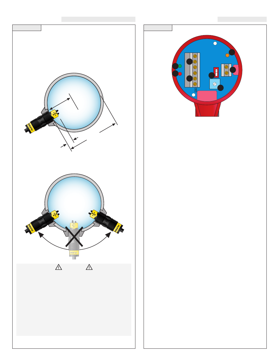
GUIDE TO CONTROLS
IN
V
E
R
IN
V
E
R
TT
+
/-
+
/-
DELA
DELAY
Y
AC
AC
AC
AC
GND
GND
NC
NC
C
C
NO
NO
R
R
P
P
In
pu
t 1
A
In
pu
t 1
A
(+)
(+)
115 VAC
220 VAC
(-)
(-)
1
3
6
4
2
5
8
7
1. Power indicator:
This green LED lights when AC power is ON.
2. Relay indicator:
This red LED will light whenever the con-
troller energizes the relay, in response to the proper condition at
the sensor inputs and after the time delay.
3. AC Power terminals:
Connection of 120 VAC power to the
controller. The setting may be changed to 240 VAC if desired.
This requires changing internal jumpers; this is covered in the
Installation section of the LC10/11 Series Manual. Polarity (neu-
tral and hot) does not matter.
4. Relay terminals (NC, C, NO):
Connect the device you wish to
control (pump, alarm etc.) to these terminals: supply to the COM
terminal, and the device to the NO or NC terminal as required.
The switched device should be a noninductive load of not more
than 10 amps; for reactive loads the current must be derated or
protection circuits used. When the red LED is ON and the relay
is in the energized state, the NO terminal will be closed and the
NC terminal will be open.
5. Invert switch:
This DIP switch reverses the logic of the relay
control in response to the sensor(s): conditions that used to ener-
gize the relay will make it turn off and vice versa.
6. Time Delay:
After the input(s) change(s) state, this control sets
a delay from 0.15 to 60 seconds before the relay will respond.
7. Input 1A indicator:
These amber LED will light immediately
whenever the appropriate sensor attached to the terminals detects
liquid, and will turn off when it is dry.
8. Input terminals:
Connect the wiring from the sensors to these
terminals. Note the polarity: (+) is a 13.5 VDC, 27 mA power
supply, and (-) is the return path from the sensor. If polarity is
reversed, the sensors will not work.
When using any type of fitting, the orientation as well as the insertion
depth of the flow switch in the pipe is critical. See the diagram below
for the recommended orientation depth.
The AT1_ series flow switch when installed must always be in con-
tact with the liquid being measured. The AG1_ series flow switch
when installed must never be submersed in liquid. Both flow switch-
es feature a 3/4" NPT threads which will allow it to be used with var-
ious types of fittings. Be sure to check the insertion depth of the flow
switch in the fitting after it is installed. See the diagram below for the
recommended insertion depth.
WARNING
The flow switch tips have a thin plastic wall which may be dam-
aged if dropped or installed improperly.
The AT17 and AT18 flow switches are designed for use in liquid.
For best results, avoid installing the AT1_ where bubbles are pre-
sent or where the tips of the switch may be out of the liquid.
The AG17 and a G18 flow switches are designed for use in gas
applications. For best results, avoid installing the AG1_ where it
may be submersed in liquid.
Note: Always install the Viton gasket with all versions of the
AT1_-_6_4 and AG1_-_6_4. The G threaded version will not
seal unless the gasket is properly installed.
1/8
P
ipe
ID
m
in.
Pip
e I
D
Ac
ce
pta
ble
Ins
ert
ion
R
an
ge