Assembly of switch pro, Safety precautions – Flowline AX1X Thermo-Flo User Manual
Page 4
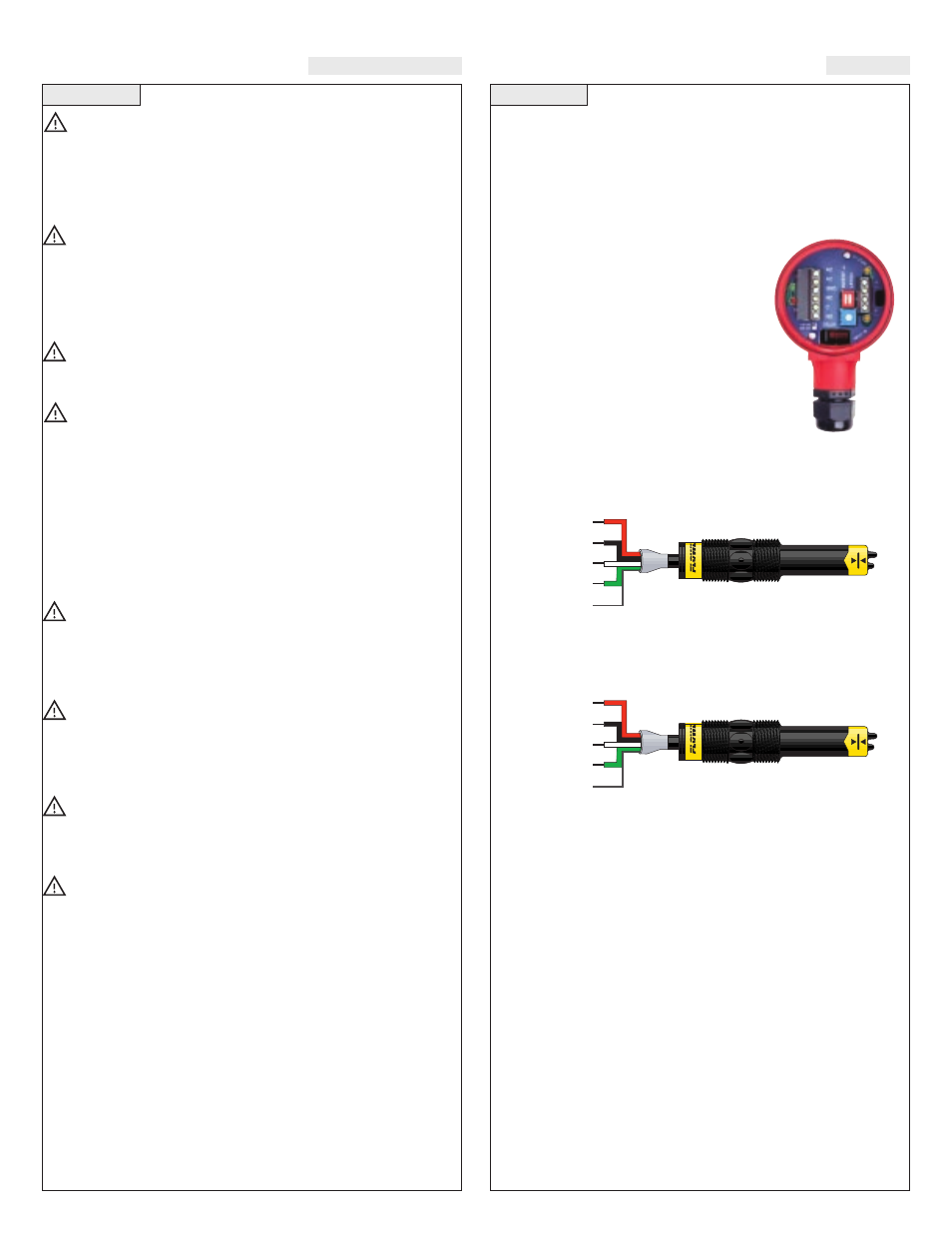
Step Five
ASSEMBLY OF SWITCH PRO™
Step Four
SAFETY PRECAUTIONS
About this Manual:
PLEASE READ THE ENTIRE MANU-
AL PRIOR TO INSTALLING OR USING THIS PRODUCT. This
manual includes information on the Switch Pro™ with Compact
Relay Controller (Flow): AT17-_6__, AT16-_6__, AG17-_6__ and
AG18-_6__. The units are identical except for the material of con-
struction and the sensors technology.
User's Responsibility for Safety:
Flowline manufactures
a wide range of liquid sensors, controllers, and mounting systems.
It is the user's responsibility to select components that are appro-
priate for the application, install them properly, perform tests of the
installed system, and maintain all components. The failure to do so
could result in property damage or serious injury.
Proper Installation and Handling:
Use a proper sealant
with all installations. Never overtighten the components. Always
check for leaks prior to system start-up.
Material Compatibility:
Polypropylene (PP, a polyolefin): Sensor, Junction Box.
Ryton: Sensor (AT1_-16__ and AG1_-16__ only).
Polyvinylidene Fluoride (PVDF): Sensor (AT1_-36__ and AG1_-36__ only).
Make sure that the application liquids are compatible with the
materials that will be wetted. To determine the chemical compati-
bility between the components and its application liquids, refer to
the Compass Corrosion Guide, available from Compass
Publications (phone 858-589-9636).
Temperature and Pressure:
Switch Pro™ is designed for
use in application temperatures up to 50° C (140° F). The assem-
bly is also designed for pressurized applications up to 150 psi (10
bar).
Wiring and Electrical:
Electrical wiring of any liquid level
control system should be performed in accordance with all applic-
able national, state, and local codes. Take care not to cut or break
the outer insulation jacket of wiring that may be immersed while
routing cables in the Switch Pro™ system. Such breaks of the liq-
uid seal of the sensor system may lead to component failure.
Flammable, Explosive and Hazardous Applications:
The AT17-_6__, AT18-_6__, AG17-_6__ and AG18-_6__ Switch
Pro™ should not be used within classified hazardous environ-
ments.
Make a Fail-Safe System:
Design a fail-safe system that
accommodates the possibility of system or power failure. In criti-
cal applications, Flowline recommends the use of redundant back-
up systems and alarms in addition to the primary system.
About Switch Pro™:
Flowline’s Switch Pro™ with Compact
Relay Controller is a single-point mounting system for installing one
flow sensor within a pipe or fume.. The compact relay controller fea-
tures a 120/240 VAC controller with a 250 VAC, 10A SPDT relay con-
tract. Switch Pro™ typically mounts horizontally through a standard
3/4" NPT (3/4” G) tank adapter.
Relay Controller:
The flow switch is
pre-wired before shipment to the 3-pole ter-
minal strip [Input 1 (+), (-) & (S)]. The tech-
nologies used to indicate flow is Thermal
Dispersion. Both the liquid and gas configu-
rations feature similar wiring/power configu-
ration. The Compact Relay Controller pro-
vides a 1/2” Conduit connection and 6 poles
for wire termination of power and relay con-
tact. Use the AC, AC and GND terminals for
providing power. Use the NC, NC and COM
terminals for interfacing to the relay contact.
Liquid (FT10-_4_5 or FT10-_4_5)
Wire Configuration:
Compact
Relay Controller
(inside shown)
RELAY
(+)
(-)
NO*
COM
Shld
Red
Black
White
Green
* Reversing the polarity of Red and Black
Gas (GT10-_4_5 or GT10-_4_5)
Wire Configuration:
RELAY
(+)
(-)
NO*
COM
Shld
Red
Black
White
Green
* Reversing the polarity of Red and Black