Wiring – Flowline GT10 Thermo-Flo User Manual
Page 5
Step Six
Step Seven
WIRING
WIRING
[Flow Condition]
Sensor
(NO)
RED
GRN
SHLD
WHT
BLK
LOAD
LOAD
OR
[+]
[-]
[Flow Condition]
Sensor
(NC)
BLK
GRN
SHLD
WHT
RED
LOAD
LOAD
OR
[+]
[-]
[Flow Condition]
Sensor
(NO)
RED
GRN
SHLD
WHT
BLK
LOAD
[Low Voltage]
[+]
[-]
[Flow Condition]
Sensor
(NC)
BLK
GRN
SHLD
WHT
RED
LOAD
[Low Voltage]
[+]
[-]
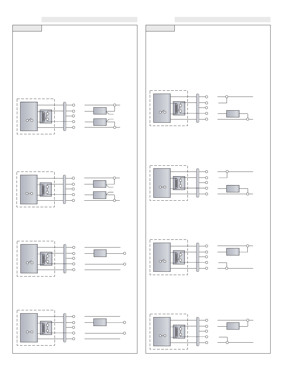
Wiring the Relay Output:
The Thermo-Flo relay output can be wired as a dry contact to a VDC
or VAC power source. Thermo-Flo does require 12 - 36 VDC power
to operate the sensor and switch the relay. All illustrations below
identify a Dry switch state as the normal position of the relay.
Switching a Normally Open DC Load:
The Red wire connects to Positive (+) of the power supply and the
Black wire connects to Negative (-). The LOAD can be attached to
either the Green or White wires. Complete the circuit by either con-
necting the Green to (+) VDC power or White to (-) VDC power (see
illustration below).
Switching a Normally Closed DC Load:
The Black wire connects to Positive (+) of the power supply and the
Red wire connects to Negative (-). The LOAD can be attached to
either the Green or White wires. Complete the circuit by either con-
necting the Green to (+) VDC power or White to (-) VDC power (see
illustration below).
Switching a Normally Open AC Load:
The Red wire connects to Positive (+) of the DC power supply and the
Black wire connects to Negative (-). The LOAD can be attached to
the Green wire and the Hot of the VAC power. Connect the White to
the Neutral of the VAC power (see illustration below).
Switching a Normally Closed AC Load:
The Black wire connects to Positive (+) of the DC power supply and
the Red wire connects to Negative (-). The LOAD can be attached to
the Green wire and the Hot of the VAC power. Connect the White to
the Neutral of the VAC power (see illustration below).
Wiring as a P-Channel or N-Channel output:
The Thermo-Flo can be substituted for either a P-Channel (PNP,
sourcing) output or a N-Channel (NPN, sinking) output.
Normally Open DC Load as a P-Channel Output:
To wire as a NO P-Channel output, follow the directions below. The
Red wire connects to Positive (+) of the power supply and the Black
wire connects to Negative (-). The Green wire is jumpered to the Red
wire while the White wire is connected to the LOAD. Jumper the
LOAD back to the Negative (-) to complete the circuit.
[Flow Condition]
Sensor
(NO)
RED
GRN
SHLD
WHT
BLK
LOAD
[+]
[-]
[Flow Condition]
Sensor
(NC)
BLK
GRN
SHLD
WHT
RED
LOAD
[+]
[-]
[Flow Condition]
Sensor
(NO)
RED
GRN
SHLD
WHT
BLK
LOAD
[+]
[-]
[Flow Condition]
Sensor
(NC)
BLK
GRN
SHLD
WHT
RED
LOAD
[+]
[-]
Normally Closed DC Load as a N-Channel Output:
To wire as a NC N-Channel output, follow the directions below. The
Black wire connects to Positive (+) of the power supply and the Red
wire connects to Negative (-). The White wire is jumpered to the Red
wire while the White wire is connected to the LOAD. Jumper the
LOAD back to the Positive (+) to complete the circuit.
Normally Open DC Load as a N-Channel Output:
To wire as a NO N-Channel output, follow the directions below. The
Red wire connects to Positive (+) of the power supply and the Black
wire connects to Negative (-). The White wire is jumpered to the
Black wire while the Green wire is connected to the LOAD. Jumper
the LOAD back to the Positive (+) to complete the circuit.
Normally Closed DC Load as a P-Channel Output:
To wire as a NC P-Channel output, follow the directions below. The
Black wire connects to Positive (+) of the power supply and the Red
wire connects to Negative (-). The Green wire is jumpered to the
Black wire while the White wire is connected to the LOAD. Jumper
the LOAD back to the Negative (-) to complete the circuit.