Specifications, Thermo-flo ultrasonic level switch, ft10 series, Set points – Flowline GT10 Thermo-Flo User Manual
Page 2
Step One
SPECIFICATIONS
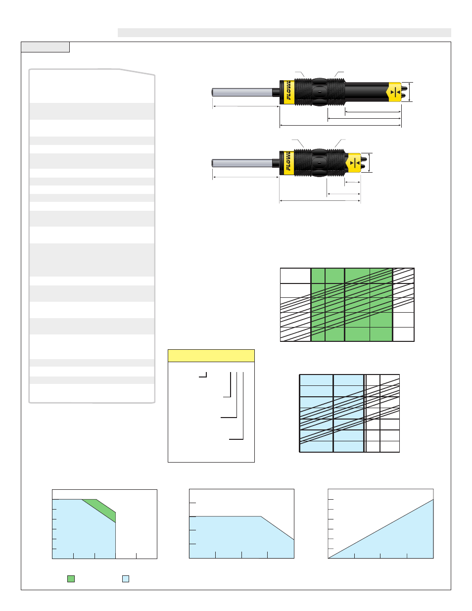
_T10 - _ _ _ 5
Medium
F - Liquid
G - Gas
Sensor Material
1 - PP
5 - PVDF
Sensor Length
3 - Short
4 - Long
Mounting Thread
0 - 3/4" NPT
2 - 3/4" ISO
Thermo-Flo Switch
1,400
1,200
1,000
800
600
400
200
0
12
18
24
30
36
Flowline Electrical Loading Limits
Acceptable
Range
Unacceptable
Range
Max. Series Resistance (Ohms)
Supply Voltage (VDC)
100
80
60
40
20
00
12
18
24
30
36
Maximum Temperature/Voltage
Derating @ Maximum Current
Acceptable
Range
Unacceptable
Range
Ambient Sensor
T
emperature (Cß)
Operating Voltage (VDC)
Set point range:
Factory set point:
Repeatability:
Response time:
Set point adjust.:
Viscosity range:
(FT10 only)
Supply voltage:
Consumption:
Contact type:
Contact rating:
Contact output:
Process temp.:
Electronics temp.:
Pressure:
Sensor rating:
Sensor material:
Cable jacket mat.:
Cable type:
Cable length:
Process mount:
Mount. gasket:
Classification:
CE compliance:
FT10: .04 to 3 fps
(.012 to .91 mps)
GT10: 1 to 90 fps
(.3 to 27 mps)
FT10: .2 fps (.06 mps)
GT10: 10 fps (3 mps)
±
.5% of set point
@ fixed temp.
1-10 seconds
Potentiometer
1-200 centipoise
12-36 VDC
70 mA maximum
(1) SPST relay
60 VA
Selectable NO/NC
F: 32˚ to 140˚
C: 0˚ to 60˚
F: -40˚ to 140˚
C: -40˚ to 60˚
150 psi (10 bar) @ 25˚
C., derated @ 1.667
psi (.113 bar) per ˚C.
above 25˚ C.
NEMA 4X (IP65)
1__5: PP-Ryton®
5__5: PVDF Kynar®
1__5: PP
5__5: FEP Teflon®
4-conductor, #22 AWG
(shielded)
Standard: 10' (3m)
Special order: 25'
(7.6m) or 50' (15.2m)
3/4" NPT (3/4" G / R)
Viton® (G version only)
General purpose
EN 61326 EMC
EN 61010-1 safety
Common Specifications:
175
150
125
100
075
050
025
000
00
20
40
60
80
100
Acceptable
Range
Unacceptable
Range
Temperature/Pressure Derating
Operating Pressure (psi)
Temperature (Cß)
PVDF PP
0.7"
(19mm)
2.8"
(71mm)
2.1"
(54mm)
4.5"
(114mm)
3/4" NPT (G 3/4")
3/4" NPT (R 3/4")
10’ Cable
(3m)
1.3"
(32mm)
0.7"
(19mm)
10’ Cable
(3m)
3.0"
(76mm)
0.7"
(19mm)
3/4" NPT (R 3/4")
3/4" NPT (R 3/4")
Thermo-Flo Ultrasonic Level Switch, FT10 Series
* all dimensions are Nominal
10
6
10
5
10
4
10
3
10
2
10
1
1
10
-1
1 10 100 150 1000
12"
8"
6"
4"
3"
2"
1"
3/4"
1/2"
90
GT10 Rate vs Velocity
Flow Rate (cfm)
Velocity (fps)
1000
100
10
1
0.1
0.01
.01 .04 .1 .2 1 3 10
6"
4"
3"
2"
1-1/2"
1"
3/4"
1/2"
12" 10" 8"
FT10 Volume vs Velocity
Flow Rate (gpm)
Velocity (fps)
Set Points:
The FT10 liquid flow switch set point is factory calibrated to
0.2 fps and the GT10 gas flow switch is set to 10 fps. To con-
vert feet/sec to GPM, please refer to the chart below.