Installation wiring, Wiring to a flowline controller – Flowline GT10 Thermo-Flo User Manual
Page 4
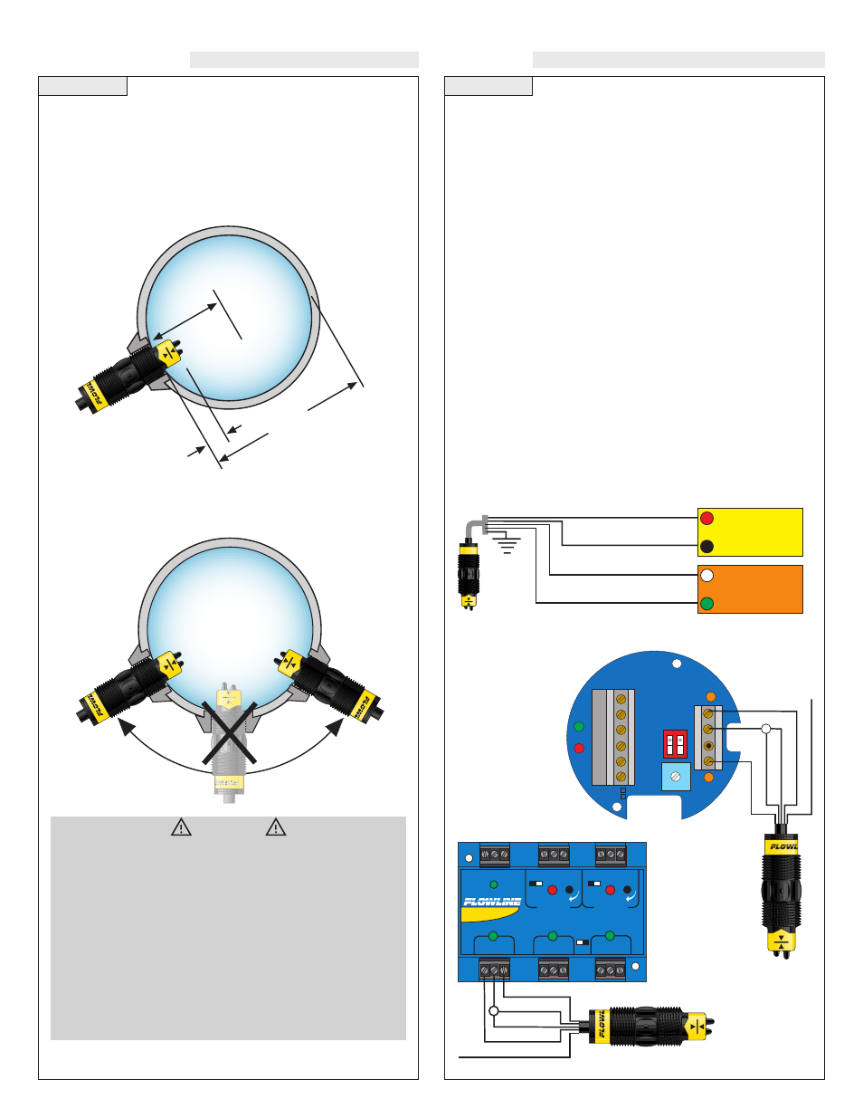
Step Four
Step Five
INSTALLATION
WIRING
When using any type of fitting, the orientation as well as the insertion
depth of the flow switch in the pipe is critical. See the diagram below
for the recommended orientation depth.
The FT10 series flow switch must always be in contact with
the liquid being measured. The GT10 series flow switch must
never be submersed in liquid. Both flow switches feature a
3/4" NPT threads which will allow it to be used with various
types of fittings. Be sure to check the insertion depth of the
flow switch in the fitting after it is installed. See the diagram
below for the recommended insertion depth.
WARNING
The flow switch tips have a thin plastic wall which may be dam-
aged if dropped or installed improperly.
The FT10 flow switch is designed for use in liquid. For best
results, avoid installing the FT10 where bubbles are present or
where the tips of the switch may be out of the liquid.
The GT10 flow switch is designed for use in gas applications.
For best results, avoid installing the GT10 where it may be sub-
mersed in liquid.
Note: Always install the Viton gasket with all versions of the
FT10-__2_. The G threaded version will not seal unless the gas-
ket is properly installed.
1/8 Pipe ID min.
Pipe ID
Acceptable
Insertion Range
Wiring to a Flowline Controller:
LC30 Series Controller
LC80 Series Controller
INVERINVER
T
+/- +/-
LALA
TCHTCH
DELA
DELAY
AC
AC
AC
AC
GND
GND
NC
NC
C
NO
NO
R
R
P
P
Input 1A
(S)
(S)
(-)
(-)
115 VAC
220 VAC
(+)
(+)
Green
Black
Shield - Not Used
White
Red
STANDARD
CONTROLLER
R E L A Y 1
R E L A Y 2
P O W E R
I N P U T 1
I N P U T 2 A
I N P U T 2 B
- +
- +
I N V E R T
D E L A Y
I N V E R T
D E L A Y
LATCH
ON OFF
Green
Red
White
Black
Not Used - Shield
Supply Voltage:
The supply voltage to the Thermo-Flo flow switch should never
exceed a maximum of 36 VDC. Use controllers or power supplies,
with a minimum output of 12 VDC or a maximum output of 36 VDC.
Required Cable Length:
Determine the length of cable required between the Thermo-Flo flow
switch and its point of termination. Allow enough slack to ensure the
easy installation, removal and/or maintenance of the sensor. The
cable length may be extended up to a maximum of 1000 feet, using a
well-insulated, 14 to 20 gauge shielded four conductor cable.
Wire Stripping:
Using a 10 gauge wire stripper, carefully remove the outer layer of
insulation from the last 1-1/4" of the sensor's cable. Unwrap and dis-
card the exposed foil shield from around the signal wires, leaving the
drain wire attached if desired. With a 20 gauge wire stripper, remove
the last 1/4" of the colored insulation from the signal wires.
Signal Output (Relay switching):
Allows the sensor to switch a small load on or off directly, using an
internal relay rated below 60 VA. The NO/NC status is set by the
polarity of the voltage feeding the red and black wires. The green
wire is the common for the relay and the white wire is the NO or NC,
depending on the polarity of red and black.
Normally Open Wiring:
Red
Black
Shield
Ground
24 VDC
Power Supply
+
-
Multimeter
(Continuity)
-
+
White
Green