Orientation maintenance – Flowline LV10 Switch-Tek User Manual
Page 6
Step Eight
Step Nine
ORIENTATION
MAINTENANCE
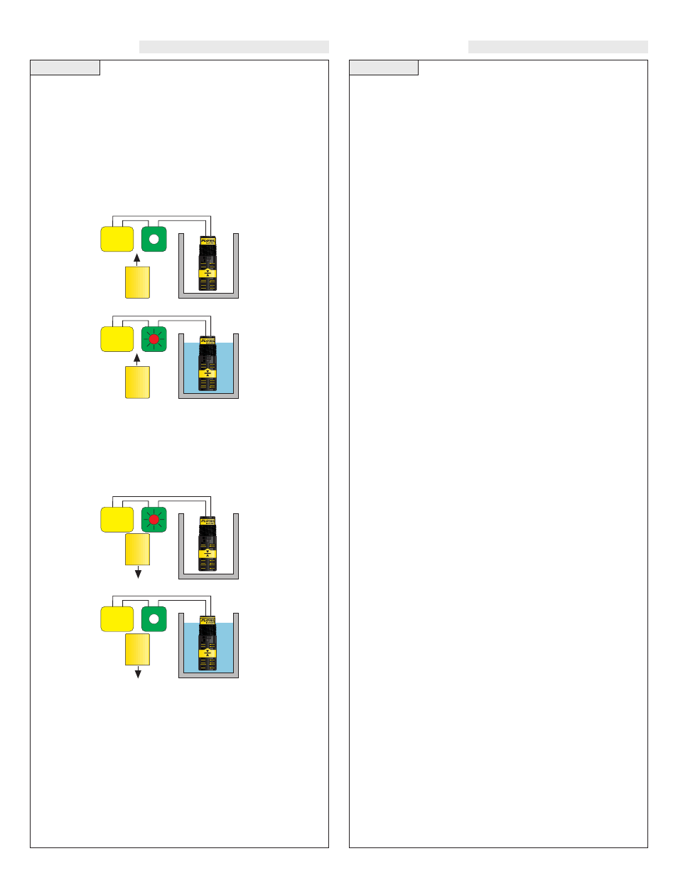
Vertical Float Level Switch (LV10-_2_1):
The LV10-_2_1 switch can be wired normally open or normally
closed for your application requirement.
Normally Open:
Only use the Black and Red wires with the LV10-_2_1. Orientate the
float upward so that the switch is in the normally open state. Normally
open is defined as the switch being open when the float is dry and
closed when the float becomes submersed. This operation is typical
for indicating a high level.
Normally Closed:
Only use the Black and Red wires with the LV10-_2_1. Orientate the
float downward so that the switch is in the normally closed state.
Normally closed is defined as the switch being closed when the float
is dry and open when the float becomes submersed. This operation is
typical for indicating a low level.
General:
While a filter shroud protects the float from particulate contamina-
tion, the switch may need to be cleaned periodically too prevent jam-
ming or sticking. The vertical buoyancy and vertical float has no
scheduled maintenance requirement, except to clean off any deposits
or scaling from the switch as necessary. It is the responsibility of the
user to determine the appropriate maintenance schedule, based on the
specific characteristics of the application liquid.
Cleaning procedure:
1. Power:
Make sure that all power to the switch, controller and/or
power supply is completely disconnected.
2. Switch removal:
If necessary, make sure that the tank is drained
well below the switch prior to removal. Carefully, remove the sen-
sor from the installation. Remove the outer screen by pushing on
the screen and turning is slightly to disconnect is from the bayo-
net connector so that the float is exposed.
3. Cleaning the switch:
Using a soft bristle brush and mild deter-
gent, carefully wash the switch. Do not use harsh abrasives such
as steel wool or sandpaper, which might damage the surface of the
sensor. Do not use incompatible solvents which may damage the
sensor's PP or PVDF plastic body. Take particular care to remove
any scaling from the float body and make sure that it moves
freely.
4. Sensor installation:
Follow the appropriate steps of installa-
tion as outlined in the Installation section of this manual.
Testing the installation:
1. Power:
Turn on power to the controller and/or power supply.
2. Immersing the switch:
Immerse the sensing tip in its applica-
tion liquid, by filling the tank up to the switches point of actua-
tion. An alternate method of immersing the switch during prelim-
inary testing is to hold a cup filled with application liquid up to
the switch's tip.
3. Test:
With the switch being fluctuated between wet and dry
states, the switch indicator light in the controller should turn on
and off. If the controller doesn't have an input indicator, use a volt-
meter or ammeter to ensure that the switch produces the correct
signal.
4. Point of actuation:
Observe the point at which the rising or
falling fluid level causes the switch to change state, and adjust the
installation of the switch if necessary.
Red
Power
Supply
Black
Red
Power
Supply
Black
Red
Power
Supply
Black
Red
Power
Supply
Black