Safety precautions installation – Flowline LV10 Switch-Tek User Manual
Page 3
Step Two
Step Three
SAFETY PRECAUTIONS
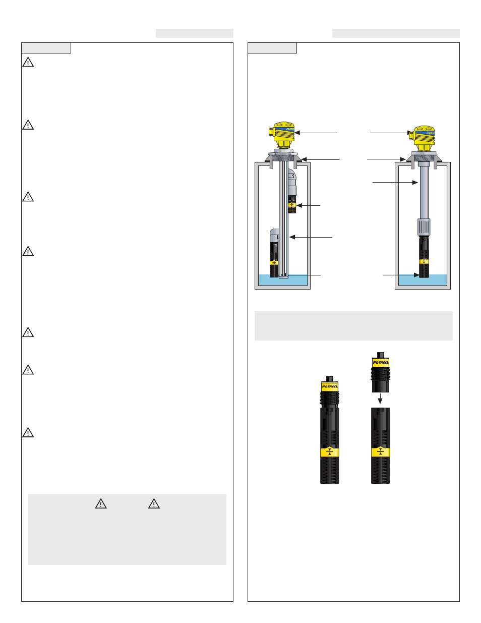
INSTALLATION
About this Manual:
PLEASE READ THE ENTIRE MANUAL
PRIOR TO
INSTALLING OR USING THIS PRODUCT. This manual
includes information on the vertical buoyancy, model LV10-_3_1,
and vertical float switch, model LV10-_2_1. Please refer to the part
number located on the sensor label to verify the exact model which
you have purchased.
User's Responsibility for Safety:
FLOWLINE manufactures a wide range of liquid level switches
and technologies. While each of these switches are designed to
operate in a wide variety of applications, it is the user's responsi-
bility to select a switch model that is appropriate for the applica-
tion, install it properly, perform tests of the installed system, and
maintain all components. The failure to do so could result in prop-
erty damage or serious injury.
Proper Installation and Handling:
Because this is an electrically operated device, only properly
trained staff should install and/or repair this product. Use a proper
sealant with all installations. Never overtighten the sensor within
the fitting, beyond a maximum of 80 inch-pounds torque. Always
check for leaks prior to system start-up.
Material Compatibility:
The LV10 level switch is available in two wetted material versions.
The switch and cable are made of Polypropylene (PP) for the
LV10-1__1. The switch is made of Polyvinylidene Fluoride
(PVDF) and cable is made of Perfluoroalkoxy (PFA) for the LV10-
5__1. Make sure that the switch is compatible with the application
liquids. To determine the chemical compatibility between the sen-
sor and its application liquids, refer to the Compass Corrosion
Guide, available from Compass Publications (858-589-9636).
Temperature and Pressure:
The LV10 series switch is designed for use in application tempera-
tures up to 80 °C, and for use at pressures up to 25 psi (2 bar) @ 25
°C., derated @ 1.667 psi (.113 bar) per °C. above 25 °C.
Wiring and Electrical:
The supply voltage used for the LV10 switch should never exceed
120 volts AC @ 15 VA for the LV10-_3_1 and 120 volts AC @ 50
VA for the LV10-_2_1. For the CE versions, the supply voltage for
the LV10 switch should never exceed 30 Vrms and 42.4 Vpeak or
60 VDC. Electrical wiring of the switch should be performed in
accordance with all applicable national, state, and local codes.
Flammable, Explosive and Hazardous Applications:
The LV10 series switch should not be used within flammable or
explosive applications unless properly connected to a approved
control device. In hazardous applications, use redundant measure-
ment and control points, each having a different sensing technolo-
gy. Refer to the National Electrical Code (NEC) for all applicable
installation requirements in hazardous locations.
Through Wall Installation:
FLOWLINE’s LV10 switch may be installed through the top wall of
a tank. The sensor has male 3/4" NPT threads and a 3/4" bayonet
adapter on the LV10-_3_1. This enables the user to mount the LV10
using either FLOWLINE's Smart Trak™ or FLOWLINE's Switch
Pak™.
Note: Avoid installing the LV10 in magnetized metal
tanks. Doing so will activate the internal reed switch.
LV10-_3_1
LV10-_3_1
3/4” threads
3/4” bayonet
WARNING
Please observe the difference in wiring and operation between
the LV10-_3_1 and the LV10-_2_1.
Avoid installing the LV10 in tanks in magnetized metal tanks.
Doing so will activate the internal reed switch.
High Level Sensor
Model LV10-_2_1
Switch Pak
LC06
Junction
Box
Low Level Sensor
Model LV10-_3_1
1/2
Coupling
Smart Trak