Wiring orientation, All models, Vertical buoyancy level switch (lv10 _1) – Flowline LV10 Switch-Tek User Manual
Page 5: Normally open, Normally closed, Black white black red, Step six step seven, Black white black red white, Black white, Black red
Step Six
Step Seven
WIRING
ORIENTATION
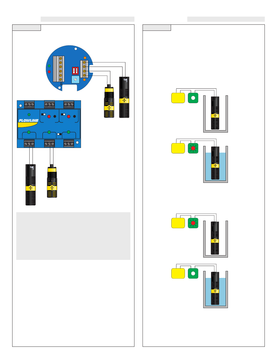
Note: Above wiring is for NO operation (open cir-
cuit when switch is dry and closed circuit when
switch is wet). To wire NC (closed circuit when dry
and open circuit when wet), use RED and BLACK
wires for the LV10-_3_1 or reverse the float for the
LV10-_2_1. Use the shield to protect the cable
from electrical noise. Attach to either the Shield
terminal or the ground terminal.
Buoyancy
Buoyancy
Float
Float
All Models:
Wiring to a FLOWLINE Controller
LC10 Series Controller
Vertical Buoyancy Level Switch (LV10-_3_1):
The LV10-_3_1 switch can be wired normally open or normally
closed for your application requirement.
Normally Open:
Use the Black and White wires for operating the LV10-_3_1 in a nor-
mally open state. Normally open is defined as the switch being open
when the float is dry and closed when the float becomes submersed.
This operation is typical for indicating a high level.
Normally Closed:
Use the Black and Red wires for operating the LV10-_3_1 in a nor-
mally closed state. Normally closed is defined as the switch being
closed when the float is dry and open when the float becomes sub-
mersed. This operation is typical for indicating a low level.
LC40 Series Controller
INVERINVER
T
+/- +/-
LALA
TCHTCH
DELAY
AC
AC
GND
NC
C
NO
R
P
Input 1A
(+)
(-)
115 VAC
220 VAC
In
pu
t 1
B
Input 1B
(+)
(-)
Black
White
Black
Red
White
Power
Supply
Black
White
Power
Supply
Black
Red
Power
Supply
Black
Red
Power
Supply
Black
STANDARD
CONTROLLER
R E L A Y 1
R E L A Y 2
P O W E R
I N P U T 1
I N P U T 2 A
I N P U T 2 B
- +
- +
I N V E R T
D E L A Y
I N V E R T
D E L A Y
LATCH
ON OFF
Black
White
Black
Red