Installation electrical – Flowline LV10 Switch-Tek User Manual
Page 4
Step Four
Step Five
INSTALLATION
ELECTRICAL
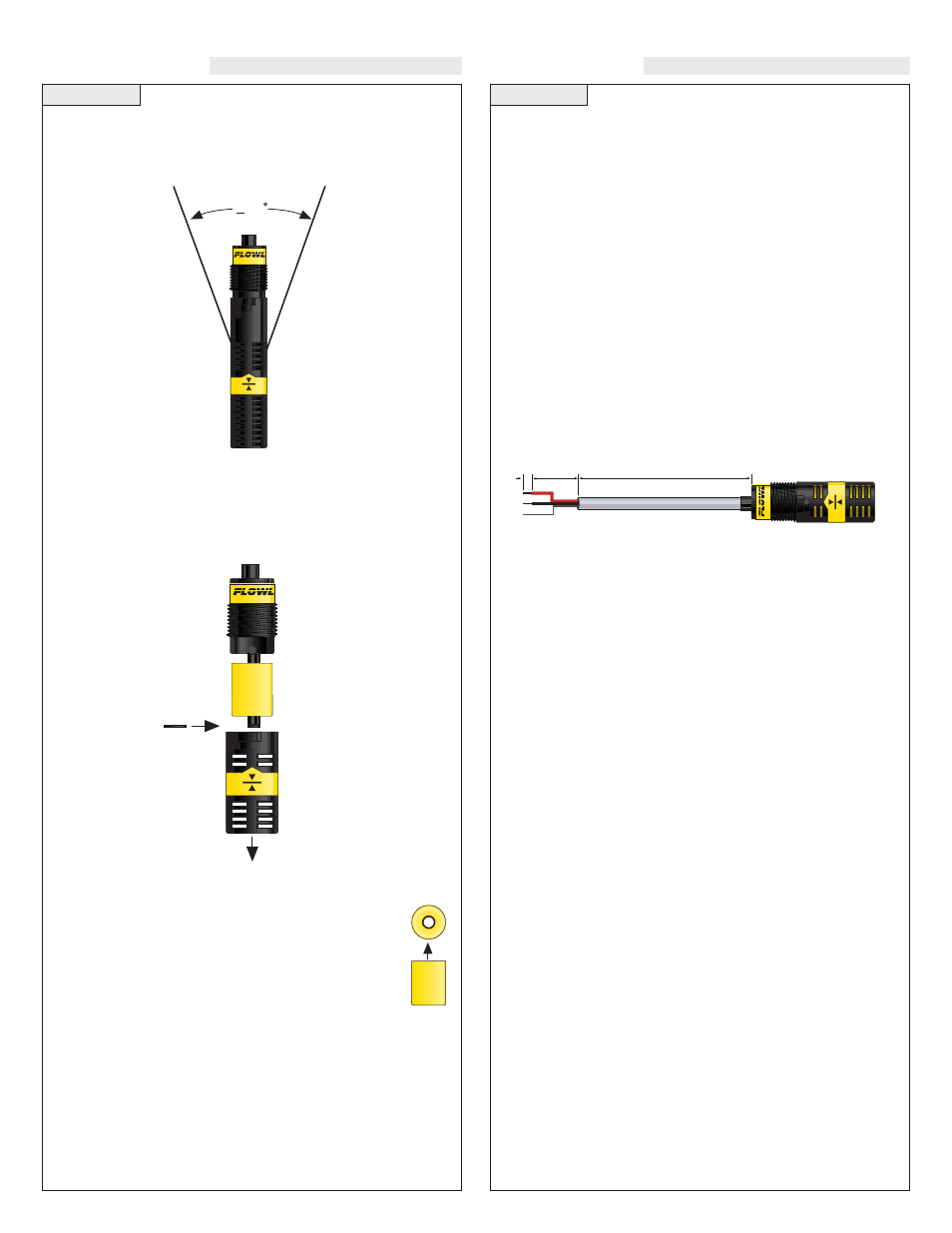
Orientation:
Mounting orientation must be kept vertical for proper operation. The
vertical buoyancy and float switches are orientated in the vertical
position ±20°.
Voltage:
The input voltage to the LV10 switch should never exceed the maxi-
mum voltage rating. FLOWLINE controllers have a built-in 13.5
VDC power supply which provides power to all of FLOWLINE’s
level switches. Alternative controllers and power supplies may also be
used with the LV10 switch.
Cable Length:
Determine the length of cable required between the LV10 series sen-
sor and its point of termination. Allow enough slack to ensure the easy
installation, removal and/or maintenance of the sensor. The cable
length may be extended up to a maximum of 1000 feet, using a well-
insulated, 18 gauge shielded wire.
Wire Stripping:
Using a 10 gauge wire stripper, carefully remove the outer layer of
insulation from the last 1-1/4" of the sensor's cable. Unwrap and dis-
card the exposed foil shield from around the signal wires, leaving the
drain wire attached if desired. With a 20 gauge wire stripper, remove
the last 1/4" of the colored insulation from the signal wires.
Removing Baffle
(LV10-_2_1 Only)
:
The vertical float, model LV10-_2_1, can be installed with out the
protective shield. To do so, remove the shield by twisting it off from
the bayonet adapter. Make sure the C-clip is added to the post to pre-
vent the float from falling off.
Output Selection
(LV10-_2_1 Only)
:
The selection of normally open or normally closed for the
LV10-_2_1 is made by the orientation of the float. The
switch arrives from the factory in the NO position (open cir-
cuit when dry). The top of the float is identified by the rough
edges at the end of the float. The smooth end is the bottom
of the float. To change to NC, rotate the float 180°.
+ 20
3/4
NPT
Float
Shield
C-Clip
?
1"
1/4"