Wiring, Models lu10 only, Intrinsically safe control drawing – Flowline LH29 Switch-Tek User Manual
Page 7: Step nine step ten
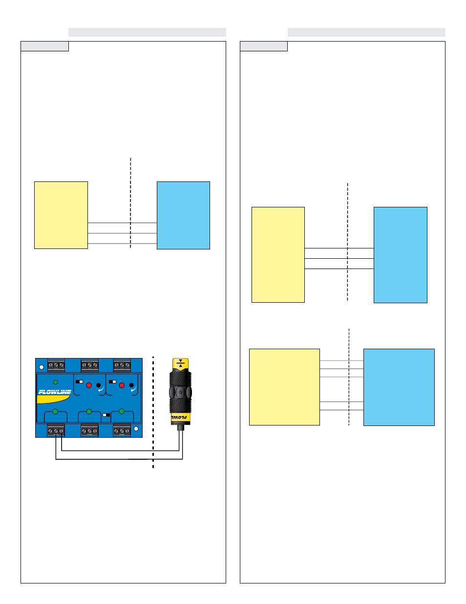
Step Nine
Step Ten
WIRING
WIRING
Models LU10-___5 Only:
The LU10-___5 level switch has been approved for use in Class I,
Groups A, B, C & D; UNDER CERTIFICATE NUMBER LR 79326-
4. DO NOT USE THE LZ12, LP15, LP10 or LO10 SERIES IN
INTRINSICALLY SAFE APPLICATIONS. The Entity parameter for
the LU10-___5 are:
Vmax = 32 VDC
Imax = 0.5 A
Ci = 0 µF
Li = 0 mH
Intrinsically Safe Control Drawing:
Wiring to a Flowline Controller:
LC90 Series Controller
4 or 20 mA Signal Output
Red Wire
Black Wire
Shield
HAZARDOUS LOCATION
Class I, Groups A, B, C & D
Class II, Groups E, F & G
Class III
NON-HAZARDOUS LOCATION
Sensor Drawing: LSD1
Rev. B 10-01-02
Sensor Models
LU10
Entity Parameters
V
max
= 32V
I
max
= 0.5A
C
i
⊕ 0
L
i
⊕ 0
Associated
Equipement
(see notes 1 and 4)
Notes:
1. CSA certified associated equipment with entity parameters.
2. V
max
≥
V
oc
,
I
max
≥ I
sc
,
C
i
+ C
cable
ʺ C
a
., L
i
+ L
cable
ʺ L
a
.
3. Installation should be in accordance with CEC Part I, or
NFPA 70.
4. Associated equipment must be installed per manufacturers
instructions
STANDARD
CONTROLLER
R E L A Y 1
R E L A Y 2
P O W E R
INPUT 1
INPUT 2A
INPUT 2B
- +
- +
INVERT
DELAY
INVERT
DELAY
LATCH
ON OFF
Black
Red
Non-Hazardous Area
Hazardous Area
Voc = 17.47 VDC
Isc = 0.4597 A
Ca = 0.494 µF
La = 0.119 µH
Vmax = 32 VDC
Imax = 0.5 A
Ci
= 0 µF
Li
= 0 µH
Models LU10-___5 Only:
The LU10-___5 level switch has been approved for use in Class I,
Division 1, Groups A, B, C & D; EEx ib IIC T6;
UNDER CERTIFICATE NUMBER LCIE 01.E6048X. DO NOT
USE THE LZ12, LP15, LP10 or LO10 SERIES IN INTRINSICALLY
SAFE APPLICATIONS. The Entity parameter for the LU10-___5
are:
North America
Europe
Vmax = 32 VDC
Ui = 32 VDC
Imax = 0.5 A
Ii = 0.5 A
Pmax = 1.3 W
Pi = 1.3 W
Ci = 0 µF
Ci = 0 µF
Li = 0 µH
Li = 0 µH
Intrinsically Safe Control Drawing:
Red Wire
Black Wire
Shield
HAZARDOUS LOCATION
Class I, Division1,
Groups A,B,C,D
EEx ib IIC T6
NON-HAZARDOUS LOCATION
Sensor Drawing: U10900
Sheet 1 of 2
Rev. B 4-02-01
Sensor Models
LU10-___5
Entity Parameters:
North America
V
max
= 32V
I
max
= 300 mA
P
max
= 1.3 W
C
i
= 0 µF
L
i
= 0 µH
Europe
U
i
= 32V
I
i
= 300 mA
P
i
= 1.3 W
C
i
= 0 µF
L
i
= 0 µH
Associated
Equipment
Entity Parameters:
North America
V
oc
≤ V
max
I
sc
≤ I
max
C
a
≥ C
i
+C
cable
L
a
≥ L
i
+L
cable
Europe
U
o
≤ U
i
I
o
≤ I
i
C
o
≥ C
i
+C
cable
L
o
≥ L
i
+L
cable
Red Wire
Black Wire
Shield
HAZARDOUS LOCATION
Class I, Division1,
Groups A,B,C,D
EEx ib IIC T6
NON-HAZARDOUS LOCATION
Sensor Drawing: U10900
Sheet 2 of 2
Rev. B 4-02-01
Sensor Models
LU10-___5
Entity Parameters for 12-32 Lines:
V
max
= 32V,�
U
i
= 32V
I
max
= 300 mA,�
I
i
= 300 mA
P
max
= 1.3 W,�
P
i
= 1.3 W
C
i
= 0 µF,�
C
i
= 0 µF
L
i
= 0 µH,�
L
i
= 0 µH
Entity Parameters for Switch Outputs:
V
max
= 32V,�
U
i
= 32V
I
max
= 500 mA,�
I
i
= 500 mA
P
max
= 1.3 W,�
P
i
= 1.3 W
C
i
= 0 µF,�
C
i
= 0 µF
L
i
= 0 µH,�
L
i
= 0 µH
Associated Equipment
Entity Parameters for 12-32 Lines:
V
oc
≤ V
max,�
U
o
≤ U
i
I
sc
≤ I
max,�
I
o
≤ I
i
C
a
≥ C
i
+C
cable,�
C
o
≥ C
i
+C
cable
L
a
≥ L
i
+L
cable,�
L
o
≥ L
i
+L
cable
Entity Parameters for Switch Outputs:
V
oc
≤ V
max,�
U
o
≤ U
i
I
sc
≤ I
max,�
I
o
≤ I
i
C
a
≥ C
i
+C
cable,�
C
o
≥ C
i
+C
cable
L
a
≥ L
i
+L
cable,�
L
o
≥ L
i
+L
cable
Green Wire
White Wire
Notes: PARAMETERS DEPEND ON OUTPUT TYPE
1.� Installation should be in accordance with CEC Part 1, or NFPA 70.
2. � Associated Equipment shall be CSA certified with entity parameters
� connected in accordance with manufacturers instructions.