Wiring – Flowline LH29 Switch-Tek User Manual
Page 6
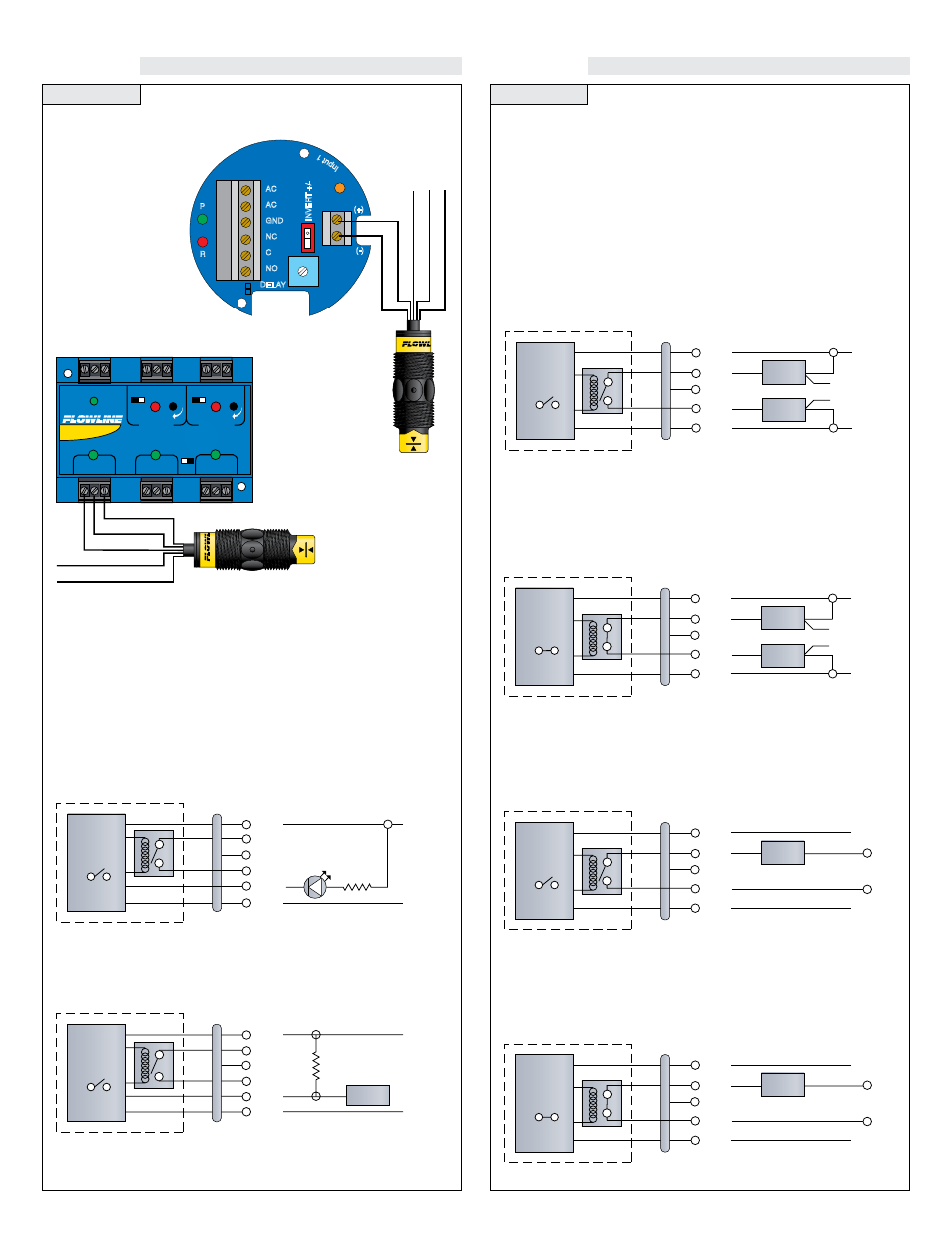
Step Seven
Step Eight
WIRING
WIRING
Wiring to a Flowline Controller:
LC10 Series Controller
(4 or 20 mA signal output)
LC40 Series Controller
(4 or 20 mA signal output)
INVER
T +/-
DELAY
AC
AC
GND
NC
C
NO
R
P
Input 1
(-)
115 VAC
220 VAC
(+)
Green - Not Used
Black
Shield - Not Used
White - Not Used
Red
STANDARD
CONTROLLER
R E L A Y 1
R E L A Y 2
P O W E R
INPUT 1
INPUT 2A
INPUT 2B
- +
- +
INVERT
DELAY
INVERT
DELAY
LATCH
ON OFF
Shld
Not Used - White *
Red
Black
Not Used - Green*
[Dry Condition]
Sensor
(NO)
RED
GRN
SHLD
WHT
BLK
LOAD
LOAD
OR
[+]
[-]
SENSOR POWER
[RED & BLK Wires]
36 VDC Max.
5 ±1 mA Dry
19 ±1 mA Wet
RELAY RATING
[GRN & WHT Wires]
60 VA Max.
[Dry Condition]
Sensor
(NC)
BLK
GRN
SHLD
WHT
RED
LOAD
LOAD
OR
[+]
[-]
SENSOR POWER
[RED & BLK Wires]
36 VDC Max.
19 ±1 mA Dry
5 ±1 mA Wet
RELAY RATING
[GRN & WHT Wires]
60 VA Max.
[AC Power]
[Dry Condition]
Sensor
(NO)
RED
GRN
SHLD
WHT
BLK
LOAD
[+]
[-]
SENSOR POWER
[RED & BLK Wires]
36 VDC Max.
5 ±1 mA Dry
19 ±1 mA Wet
RELAY RATING
[GRN & WHT Wires]
60 VA Max.
[AC Power]
[Dry Condition]
Sensor
(NC)
BLK
GRN
SHLD
WHT
RED
LOAD
[+]
[-]
SENSOR POWER
[RED & BLK Wires]
36 VDC Max.
19 ±1 mA Dry
5 ±1 mA Wet
RELAY RATING
[GRN & WHT Wires]
60 VA Max.
Wiring the Relay Output:
The Switch-Tek™ relay output can be wired as a dry contact to a
VDC or VAC power source. Switch-Tek™ does require 12 - 36 VDC
power to operate the sensor and switch the relay. All illustrations
below identify a Dry switch state as the normal position of the relay.
Switching a Normally Open DC Load:
The Red wire connects to Positive (+) of the power supply and the
Black wire connects to Negative (-). The LOAD can be attached to
either the Green or White wires. Complete the circuit by either con-
necting the Green to (+) VDC power or White to (-) VDC power (see
illustration below).
Switching a Normally Closed DC Load:
The Black wire connects to Positive (+) of the power supply and the
Red wire connects to Negative (-). The LOAD can be attached to
either the Green or White wires. Complete the circuit by either con-
necting the Green to (+) VDC power or White to (-) VDC power (see
illustration below).
Switching a Normally Open AC Load:
The Red wire connects to Positive (+) of the DC power supply and the
Black wire connects to Negative (-). The LOAD can be attached to
the Green wire and the Hot of the VAC power. Connect the White to
the Neutral of the VAC power (see illustration below).
Switching a Normally Closed AC Load:
The Black wire connects to Positive (+) of the DC power supply and
the Red wire connects to Negative (-). The LOAD can be attached to
the Green wire and the Hot of the VAC power. Connect the White to
the Neutral of the VAC power (see illustration below).
[Dry Condition]
Sensor
(NO)
RED
GRN
SHLD
WHT
YEL
BLK
[+]
[-]
SENSOR POWER
[RED & BLK Wires]
36 VDC Max.
5 ±1 mA Dry
19 ±1 mA Wet
RELAY RATING
[GRN & WHT Wires]
60 VA Max.
MAINT. ALARM
[YEL Wire]
NPN Transistor
10 mA Max.
2.2K
[Dry Condition]
Sensor
(NO)
RED
GRN
SHLD
WHT
YEL
BLK
PLC
[+]
[-]
SENSOR POWER
[RED & BLK Wires]
36 VDC Max.
5 ±1 mA Dry
19 ±1 mA Wet
RELAY RATING
[GRN & WHT Wires]
60 VA Max.
MAINT. ALARM
[YEL Wire]
NPN Transistor
10 mA Max.
10K
24 VDC
Maintenance Alarm (LZ12 Vibration only):
For optimum performance and proactive maintenance, the sensor
automatically adjusts for coating, and if necessary, outputs a preven-
tative maintenance alarm. The Yellow wire is a NPN transistor
designed to switch when a build-up of material prevents the vibration
switch from operating at its operational frequency. Use the Yellow
wire to identify when the Vibration switch requires cleaning.
To wire the maintenance output wire to an LED, follow the wiring dia-
gram below. The Yellow wire is connected to the LED and a 2.2kΩ
resister in series and referenced back to the (+) of the power supply.
To wire the maintenance output wire to an PLC, follow the wiring dia-
gram below. The Yellow wire is connected to the PLC input with a 10
kΩ resister parallel to the PLC input and the (+) of the power supply.