Installation electrical – Flowline LH29 Switch-Tek User Manual
Page 5
Step Five
Step Six
INSTALLATION
ELECTRICAL
Through Wall Installation:
Flowline’s Switch-Tek™ level switches may be installed through the
top, side or bottom of a tank wall. The sensor has male 3/4" NPT
threads on either side of a 15/16" wrench flat. This enables the user to
select the sensor’s mounting orientation, installed outside of the tank
in, or inside of the tank out.
Supply Voltage:
The supply voltage to the Switch-Tek™ level switch should never
exceed a maximum of 36 VDC. Flowline controllers have a built-in
13.5 VDC power supply which provides power to all of Flowline’s
electrically powered sensors. Alternative controllers and power sup-
plies, with a minimum output of 12 VDC up to a maximum output of
36 VDC, may also be used with the Switch-Tek™ level switch.
Required Cable Length:
Determine the length of cable required between the Switch-Tek™
level switch and its point of termination. Allow enough slack to
ensure the easy installation, removal and/or maintenance of the sen-
sor. The cable length may be extended up to a maximum of 1000 feet,
using a well-insulated, 14 to 20 gauge shielded four conductor cable.
Wire Stripping:
Using a 10 gauge wire stripper, carefully remove the outer layer of
insulation from the last 1-1/4" of the sensor's cable. Unwrap and
discard the exposed foil shield from around the signal wires, leaving
the drain wire attached if desired. With a 20 gauge wire stripper,
remove the last 1/4" of the colored insulation from the signal wires.
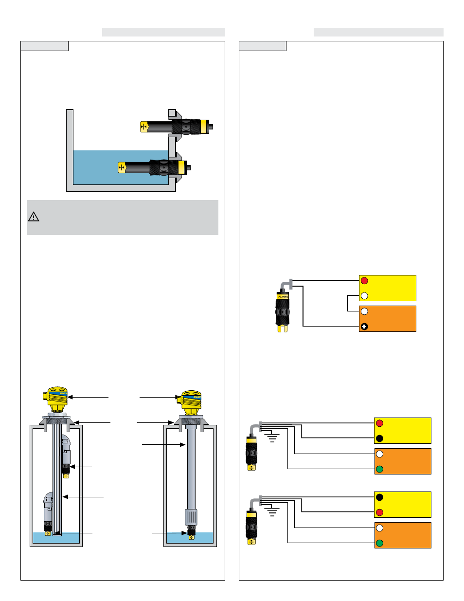
Signal Outputs (Current sensing):
The standard method used by Flowline controllers; this technology uses
only two wires (Red and Black). The sensor draws 5 mA when it is dry,
and 19 mA when wet. NC/NO status must be set by the controller. The
White and Green wires are not used.
Smart Trak™ Installation:
Flowline’s Smart Trak LM10 series mounting system is an in-tank
fitting which enables users to install up to four FLOWLINE sensors
of any technology, to any depth, along the entire length of track.
Smart Trak may be installed through the top wall of any tank using a
standard 2" NPT tank adapter. If no tank top installation is available,
Flowline's side mount bracket, LM50-1001, enables Smart Trak to be
installed directly to the side wall of a tank. Do not use PFA Teflon
sensors with Smart-Trak.
Switch Pak™ Installation:
Flowline’s Switch Pak LM45 series mounting system is an in-tank
fitting which enables users to install one FLOWLINE sensor, of any
technology, to a specific depth. The Flowline sensor may be installed
onto the 3/4" NPT adapter at the end of the Switch Pak. Switch Pak
may be installed through the top wall of any tank using a standard 2"
NPT tank adapter. Flowline's side mount bracket, model LM50-1001,
may also be used if top wall installation is not available.
Signal Output (Relay switching):
Allows the sensor to switch a small load on or off directly, using an
internal 1A relay (60 VAC/60 VDC). Only model LU10-___5 uses the
relay and features 4 wires (red, black, white and green) and a shield
wire. The NO/NC status is set by the polarity of the voltage feeding
the red and black wires. The green wire is the common for the relay
and the white wire is the NO or NC, depending on the polarity of red
and black.
Switch-Tek
High Level Switch
Switch Pak
LC06
Junction
Box
Switch-Tek
Low Level Switch
1/2
Coupling
Smart Trak
Red
Black
Shield
Ground
24 VDC
Power Supply
+
-
Multimeter
(Continuity)
-
+
White
Green
Red
24 VDC
Power Supply
+
-
Multimeter
(mA)
-
+
Black
Always install the 3/4” Viton gasket with the metric (long
sensor length) versions of the L___-__2_. The G threaded
version of the Switch-Tek™ will not seal unless the gasket is
installed properly.
Normally Open Wiring:
Normally Closed Wiring:
Black
Red
Shield
Ground
24 VDC
Power Supply
+
-
Multimeter
(Continuity)
-
+
White
Green