Assembly of switch car, Maintenance – Flowline AX23 Smart Trak User Manual
Page 8
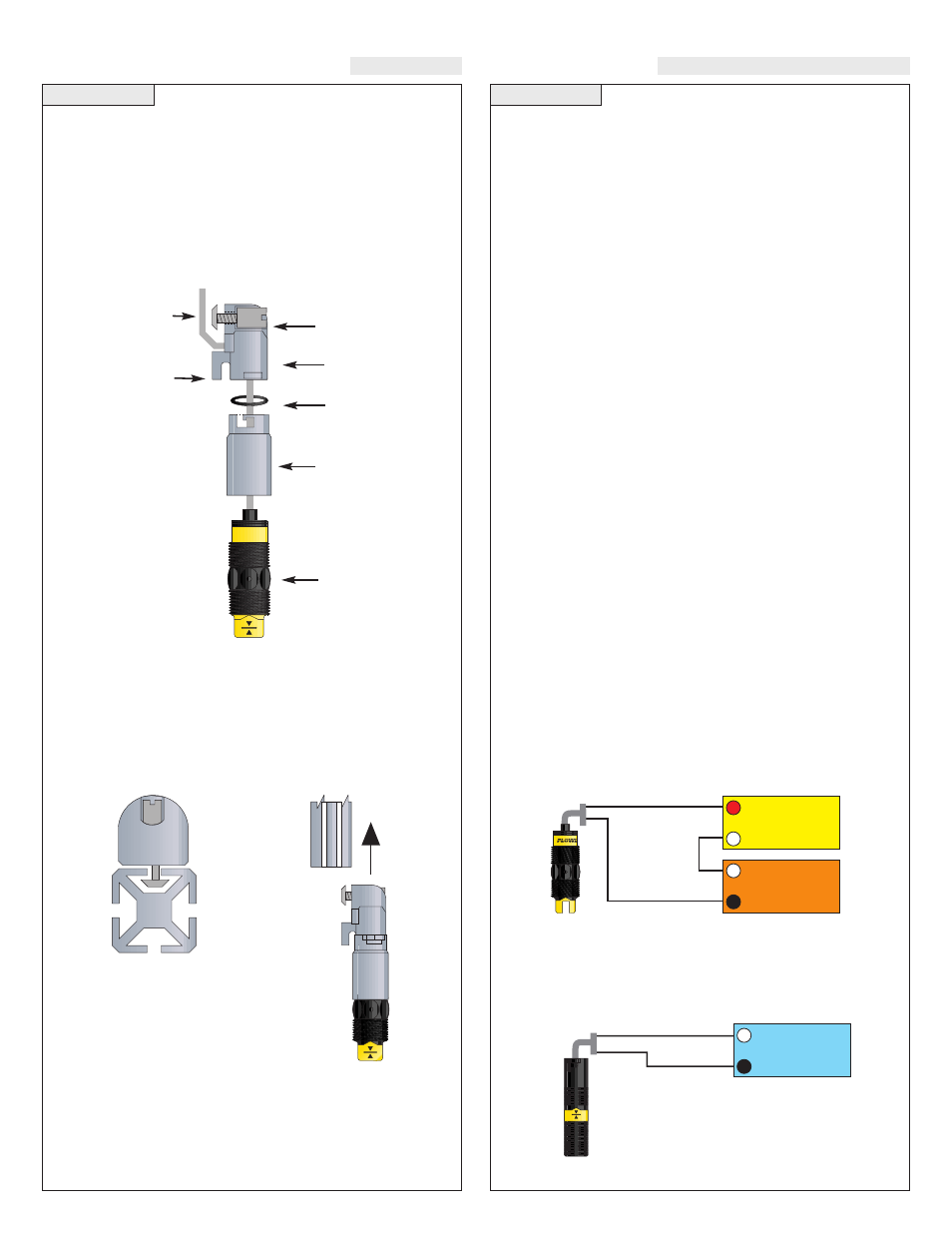
Step Eleven
ASSEMBLY OF SWITCH CAR
Step Twelve
MAINTENANCE
General:
The Smart Trak™ with Compact Junction Box requires
no periodic maintenance except cleaning as required. It is the respon-
sibility of the user to determine the appropriate maintenance schedule,
based on the specific characteristics of the application liquids.
Cleaning Procedure:
1. Power:
Make Sure that all power to the sensor, controller and/or
power supply is completely disconnected.
2. Sensor Removal:
Make sure that the tank is in a state where it
is safe to remove the sensors. Carefully, remove the Smart Trak™
from the installation.
3. Cleaning the Sensor:
Use a soft bristle brush and mild deter-
gent, carefully wash the Smart Trak™. Do not use harsh abra-
sives such as steel wool or sandpaper, which might damage the
surface sensor. Do not use incompatible solvents which may
damage the sensor's PP or Ryton plastic body.
4. Sensor Installation:
Follow the appropriate steps of installa-
tion as outlined in the installation section of this manual.
Controller Logic:
1. Power LED:
Make sure the Green power LED is On when
power is supplied to the controller.
2. Input LED(s):
The input LED(s) on the controller will be
Amber when the switch(es) is/are wet and Off when the
switch(es) is/are dry. Note: see Step 5 regarding reed switches. If
the LED's are not switching the input LED, test the level switch.
3. Relays:
When both inputs are wet (Amber LED's On), the relay
will be energized (Red LED On). After that, if one switch
becomes dry, the relay will remain energized. Only when both
switches are dry (both amber LED's Off) will the controller de-
energize the relay. The relay will not energize again until both
switches are wet. See the Relay Latch Logic Chart below for fur-
ther explanation.
Current Test (Ultrasonic and Vibration only):
Used to verify if the sensor is indicating a wet or dry condition. This
test uses only two wires (Red and Black). The sensor draws 5 mA
(ultrasonic) or 8 mA (vibration) when it is dry, and 19 mA when wet.
The White and Green wires are not used.
Contact Test (Buoyancy only):
Used to verify if the reed switch is switching between dry (open) and
wet (closed). Check for continuity across Black and White (open for
dry and closed for wet). Checking across Black and Red will result
in a closed when dry and open when wet condition.
Red
24 VDC
Power Supply
+
-
Multimeter
(mA)
-
+
Black
White
Black
Multimeter
(Continuity)
-
+
Normally Open
(Dry)
Sensor car and bayonet adapter:
The sensor car assembly is the heart of the Smart Trak™ system. It
slides in the grooves of the track, and is locked into position by a plas-
tic bolt and screw. The bayonet to 3/4" NPT adapter has a female 3/4"
NPT fitting on one end where the sensor (not included) will screw in,
and a bayonet fitting on the other end that attaches it onto the sensor
car with a slight turn, with an O-ring in-between to provide tension
for the push-and-turn connection.
Switch Car Kit Assembly Drawing (Side View)
Inventory:
One switch car kit (LM30-10_1) consists of the following parts:
1 Locking bolt
1 Locking Nut
1 Sensor car
1 O-ring
1 Bayonet to 3/4” NPT adapter
Switch Car Kit to Smart Trak™
(Top View)
(Side View)
Determine the Proper Wire Length:
Don’t make the mistake of trimming the sensor wires too short before
the process is tested. If the sensors might need to be lowered in the
future, leave sufficient slack in the wires to allow for future adjust-
ment. This extra wire may be stored in the bottom of the terminal strip
housing, or elsewhere above the compression fitting.
Sensor
Wire
Shoe
Sensor Lock
Bolt & Nut
Sensor
Car
O-ring
Flowline
Sensor
Bayonet to
3/4” NPT
Adapter