Wiring, Assembly of smart trak – Flowline AX23 Smart Trak User Manual
Page 7
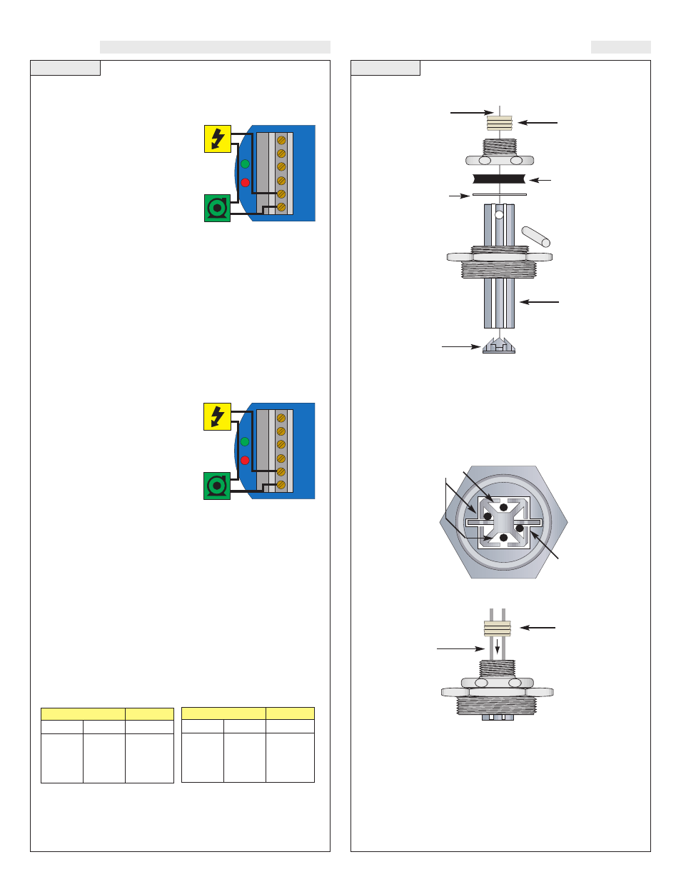
Step Nine
WIRING
Smart Trak™ Assembly Drawing (Side View)
Inventory:
One Smart Trak™ kit (LM10-1__1) includes the following parts:
1 Seal Plug
1 Top compression fitting
1 Wire gasket
1 Thrust Plate
1 Locking pin
1 2" NPT fitting
1 Track
1 End cap
2 Wire retainer clips (not shown)
Smart Trak™ Assembly Drawing (Top View):
Seal Plug Assembly Drawing (Side View)
Seal Plug
Seal Plug
Sensor Wire
Wire Gasket
Thrust Plate
Locking Pin
2” NPT
Fitting
2” NPT
Fitting
Cable
Cable
must fit
into side of
track next
to locking pin
Track
End cap
Wires
Top Compression
Fitting
Top Compression
Fitting
Step Ten
ASSEMBLY OF SMART TRAK™
Automatic Fill:
This system consists of a tank with a high and
low level sensor, and a pump or valve that is operated by the con-
troller. Proper fail-safe design for this system is to stop filling if
power is lost. Therefore, we connect
the pump/valve to the NO side of the
relay. When energized, the device
will activate and fill the tank. The
relay LED will correspond directly to
the ON/OFF status of the
pump/valve. NOTE: If the pump
motor load exceeds the rating of
relay controller, a stepper relay of
higher capacity must be used as part of the system design.
Determining the settings of LATCH and INVERT
This is the way the system must operate:
•
When both the high and low sensors are dry, the device should
activate, starting to fill the tank.
•
When the low sensor gets wet, the device should stay ON.
•
When the high sensor gets wet, the device should turn OFF.
Latch:
In any two-sensor control system, LATCH must be ON.
Invert:
Referring to the logic chart in Step Nine, we look for the set-
ting that will de-energize the relay (start the pump) when both inputs
are wet (Amber LEDs). In this system, Invert should be ON.
Automatic Empty:
Note that a
similar system logic can be used for
an automatic empty operation simply
by controlling a pump/valve that
takes fluid out of the tank instead of
into it. Connect the pump/valve to
the NO side of the relay. When ener-
gized, the device will activate and
empty the tank.
Determining the settings of LATCH and INVERT
This is the way the system must operate:
•
When both the high and low sensors are wet, the device should
activate, starting to empty the tank.
•
When the high sensor gets dry, the device should stay ON.
•
When the low sensor gets dry, the device should turn OFF.
Latch:
In any two-sensor control system, LATCH must be ON.
Invert:
Referring to the logic chart in Step Nine, we look for the set-
ting that will de-energize the relay (start the pump) when both inputs
are wet (Amber LEDs). In this system, Invert should be OFF.
AC
AC
GND
NC
C
NO
R
P
Pump
AC
AC
GND
NC
C
NO
R
P
Pump
Relay Latch Logic Table:
With Latch ON, the relay will actu-
ate when INPUT 1A and INPUT 1B are in the same condition. The relay
will not change its condition until both inputs reverse their state.
Input1A
ON
OFF
ON
OFF
Input1B
ON
ON
OFF
OFF
Relay
ON
No Change
No Change
OFF
Invert OFF
Latch Off
Input1A
ON
OFF
ON
OFF
Input1B
ON
ON
OFF
OFF
Relay
OFF
No Change
No Change
ON
Invert OFF
Latch Off