Guide to controls, Wiring, Vac power input wiring – Flowline AX23 Smart Trak User Manual
Page 6: Relay input wiring, Strobe alert output
Step Seven
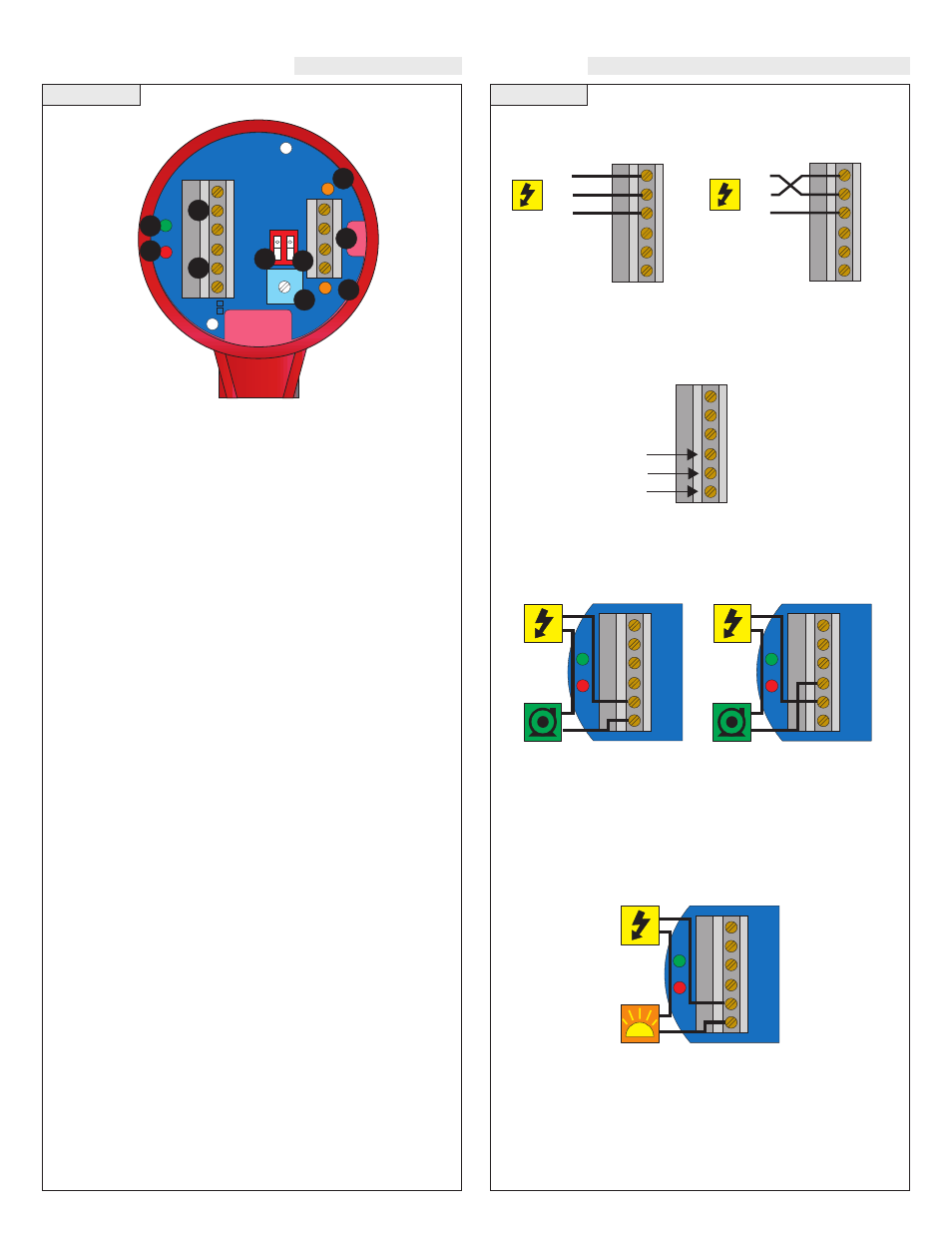
GUIDE TO CONTROLS
Step Eight
WIRING
INVERINVER
T
+/- +/-
LALA
TCHTCH
DELAY
AC
AC
GND
NC
C
NO
R
R
P
P
Input 1A
(+)
(-)
115 VAC
220 VAC
Input 1B
(+)
(-)
1
3
7
4
2
5
6
8
9
8
1. Power indicator:
This green LED lights when AC power is ON.
2. Relay indicator:
This red LED will light whenever the con-
troller energizes the relay, in response to the proper condition at
the sensor inputs and after the time delay.
3. AC Power terminals:
Connection of 120 VAC power to the
controller. The setting may be changed to 240 VAC if desired.
This requires changing internal jumpers; this is covered in the
Installation section of the LC10/11 Series Manual. Polarity (neu-
tral and hot) does not matter.
4. Relay terminals (NC, C, NO):
Connect the device you wish to
control (pump, alarm etc.) to these terminals: supply to the COM
terminal, and the device to the NO or NC terminal as required.
The switched device should be a noninductive load of not more
than 10 amps; for reactive loads the current must be derated or
protection circuits used. When the red LED is ON and the relay
is in the energized state, the NO terminal will be closed and the
NC terminal will be open.
5. Invert switch:
This DIP switch reverses the logic of the relay
control in response to the sensor(s): conditions that used to ener-
gize the relay will make it turn off and vice versa.
6. Latch switch:
This DIP switch determines how the relay will be
energized in response to the two sensor inputs. When LATCH is
OFF, the relay responds to sensor Input 1A only; when LATCH is
ON, the relay will energize or de-energize only when both sensors
(1A and 1B) are in the same condition (wet or dry). The relay will
remain latched until both sensors change states.
7. Time Delay:
After the input(s) change(s) state, this control sets
a delay from 0.15 to 60 seconds before the relay will respond.
8. Input 1A and 1B indicator:
These amber LEDs will light
immediately whenever the appropriate sensor attached to the ter-
minals detects liquid, and will turn off when it is dry.
9. Input terminals:
Connect the wiring from the sensors to these
terminals: A to the upper pair, B to the lower pair. Note the polar-
ity: (+) is a 13.5 VDC, 27 mA power supply, and (-) is the return
path from the sensor. If polarity is reversed, the sensors will not
work.
VAC Power Input Wiring:
Observe the labeling on the con-
troller. Note: Polarity does not matter with the AC input terminal.
Relay Input Wiring:
The relay is a single pole, double throw
type rated at 250 Volts AC, 10 Amps. The terminals Normally Open
(NO) and Normally Closed (NC) will be used in different applica-
tions. Remember that the "normal" state is when the relay coil is de-
energized and the Red relay LED is OFF (de-energized).
A typical application for the Smart Trak™ with Compact Relay
Controller is to operate a pump or valve between the two set points
(automatic fill or empty). In this application, a pump or valve can be
wired to either the Normally Open (NO) or Normally Closed (NC)
side of the relay.
AC
AC
GND
NC
C
NO
R
P
Strobe
HOT
NRTL
GND
AC
AC
GND
NC
C
NO
AC
AC
GND
NC
C
NO
HOT
NRTL
GND
AC
AC
GND
NC
C
NO
Relay
Terminals
Strobe Alert Output
With the Strobe Alert wired NO, the strobe will flash when the Red
LED is ON (Invert OFF). The strobe will flash when the Red LED is
OFF when wired NC or by turning the Invert ON. If the strobe is
wired NC and the Invert is ON, the strobe will flash when the Red
LED is ON (same as NO wiring and Invert OFF).
With the Latch OFF, the status of the strobe is only effected by Input
1A (Input 1B will be ignored). With the Latch ON, the status of the
strobe is only changes when both Inputs are in the same state. For
example, with Invert ON, the Strobe will flash when both Inputs
become Wet. The strobe will continue to flash until both Inputs
become dry.
AC
AC
GND
NC
C
NO
R
P
Pump
AC
AC
GND
NC
C
NO
R
P
P mp
NO Wiring
NC Wiring
Power to
Smart Trak
not shown.
Power to
Smart Trak
not shown.
Power to
Smart Trak
not shown.