Flowline LU78 EchoSwitch User Manual
Page 24
24 of 34
MN300282
Rev A
ELECTRICAL (cont.)
Step Six
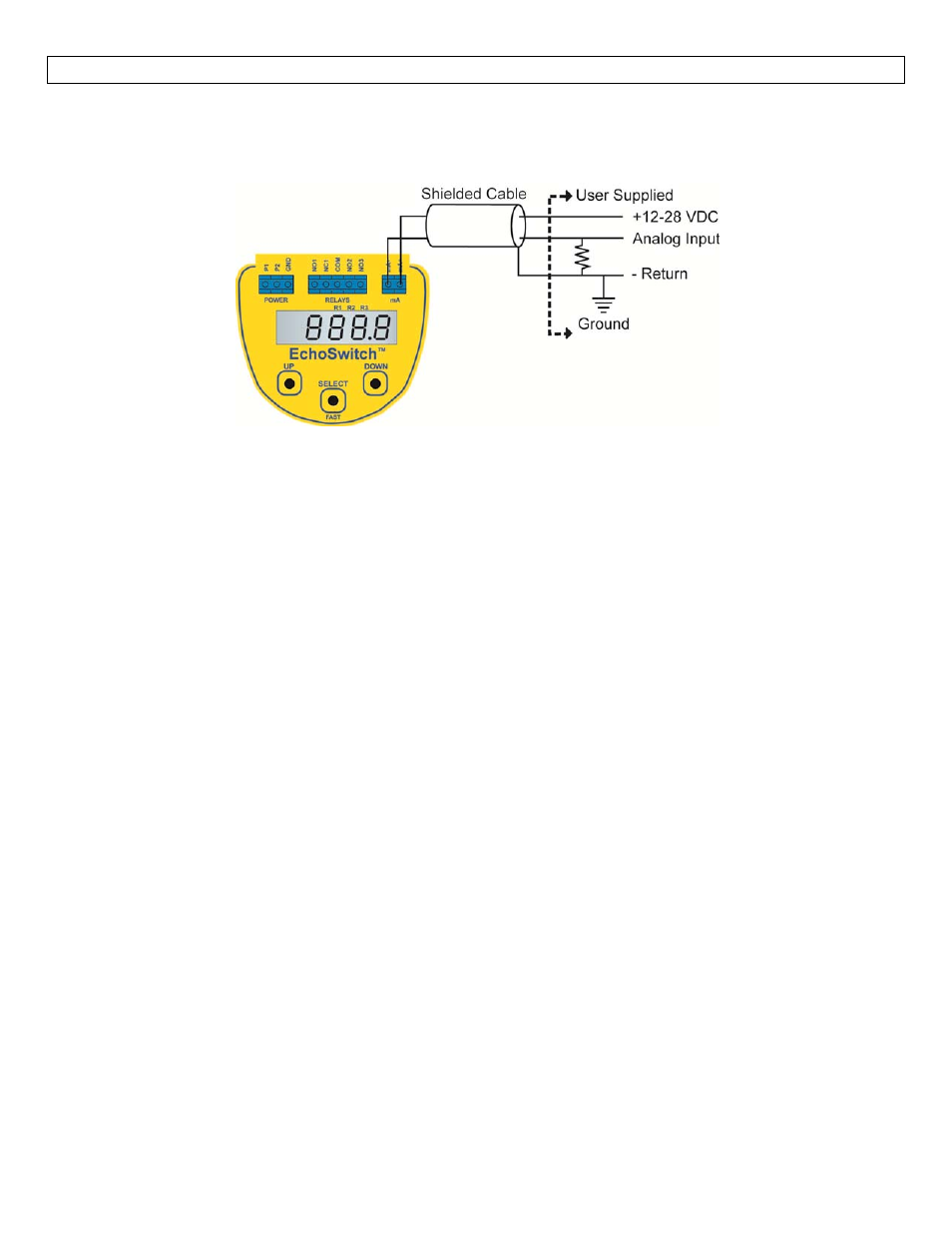
Analog Output (4/20 mA): The analog output of the EchoSwitch® is a sinking 4/20 mA control circuit. The
typical way to use this feature is to connect a positive supply to the MA+ input and to sense the current flow
out of the MA‐ output with a sampling resistor as shown in the following diagram.
The cabling should be a shielded twisted pair to minimize EMI interference. Typically 20 to 24 gauge wire is
used in this application. The analog output of the EchoSwitch® is isolated from the AC power via optocoupler
isolation.
Note – 95 to 250 VAC power is required to provide power to the EchoSwitch® for basic operation.
This manual is related to the following products: