Installation maintenance – Flowline LU30 EchoTouch User Manual
Page 6
Step Eight
Step Nine
INSTALLATION
MAINTENANCE
LOST Signal:
A reading of LOST in the display of the LU30 indicates the transmit-
ter is not receiving a valid return signal. If LOST appears, please
check the following troubleshooting items:
1. Beam cone interference such as the side wall, ladders, seams,
rungs or pipes within the LU30's beam cone.
2. Proper installation such that the LU30 is installed level and free
from interference from the installation fitting.
3. Sufficient power being supplied to the LU30. The LU30 requires
14-36 VDC power with a minimum supply of 200 mA.
4. Proper programming of the TANK function. For best results, set
the TANK function as the distance from the bottom of the tank to
the bottom of the transmitter.
5. Make sure that the transmitter is not installed at an angle. Even a
5 degree offset can reduce the signal return strength greatly.
Current is always 4mA or 20 mA:
If the output of the LU30 is always reading 4mA or 20 mA, check the
input values for the LU30. The display of the LU30 reads to the 1/10
of an inch or cm. A display of 1234 is 123.4" and not 1234".
Other Hints:
When checking the EC4 and EC20 values, the first value which
appears after EC4 or EC20 is the current distance from the bottom of
the transmitter to the surface of the liquid. Pressing either the [
s] or
[
t] buttons will then show the actual value in memory.
General:
The LU30 series sensor itself requires no periodic maintenance
except cleaning as required. It is the responsibility of the user to deter-
mine the appropriate maintenance schedule, based on the specific
characteristics of the application liquids.
Cleaning Procedure:
1.
Power:
Make Sure that all power to the sensor, controller and/or
power supply is completely disconnected.
2.
Sensor Removal:
In all through-wall installations, make sure
that the tank is drained well below the sensor prior to removal.
Carefully, remove the sensor from the installation.
3.
Cleaning the Sensor:
Use a soft bristle brush and mild deter-
gent, carefully wash the LU30 series sensor. Do not use harsh
abrasives such as steel wool or sandpaper, which might damage
the surface sensor. Do not use incompatible solvents which may
damage the LU30's Polypropylene or PVDF plastic body.
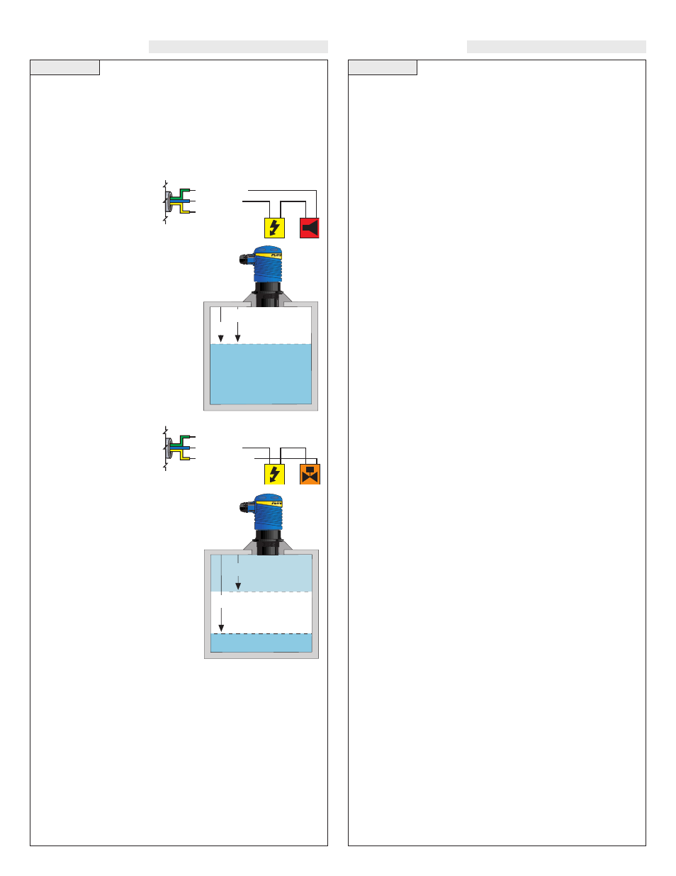
Internal Relay:
The LU30 series contains a 250 VAC, 10A, 1/2 Hp internal relay. The
relay is actuated by the HSET and LSET settings. While this manual
offers some examples and suggestions to help explain the operation of
the relay, such examples are for information only and are not intend-
ed as a complete guide to installing any specific system.
High Level Alarm:
The goal is to make sure the
liquid does not rise above a
certain point. If it does, an
alarm sounds alerting the operator to a high level
condition. Wire the hot lead of the alarm to the
Green NC relay wire. Also make sure the HSET
and LSET settings are programmed correctly.
Typically the values are set at the same distance
away from the LU30. In the normal operation
state, the LU30’s relay will remain
energized, keeping the alarm circuit
open. When the alarm level has been
reached, the relay de-energizes and
activates the alarm. To change to a low
level alarm, re-wire the alarm from the
Green NC wire to the Yellow NO wire.
Automatic Fill:
The goal is to fill the tank. A
valve is opened (energized)
when a low level is reached
and closed (de-energized)
when a high level is reached. Wire the hot lead
of the valve to the Yellow NO relay wire. Make
sure the HSET and LSET settings are pro-
grammed correctly. Typically the values are set
with the HSET as the valve close and the LSET
as the valve open. A pump or solenoid
can be substituted for the exact same
operation. When the low level is
reached, the system will start to fill the
tank. The tank will continue to fill until
the level reaches the high point. The
system stops filling until the low level
is reached again. To change to an auto-
matic empty application, re-wire the
system from the Yellow NO wire the
the Green NC wire.
- G r e e n
- B l u e
- Ye l l o w
NC
COM
NO
- G r e e n
- B l u e
- Ye l l o w
NC
COM
NO
HSET
LSET
De-Energized
Relay
Energized Relay
HSET
LSET
De-Energized
Relay
Energized Relay