Safety precautions definitions – Flowline LU30 EchoTouch User Manual
Page 3
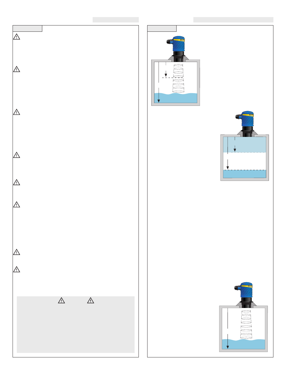
Step Two
Step Three
SAFETY PRECAUTIONS
DEFINITIONS
About this Manual:
PLEASE READ THE ENTIRE MANUAL PRIOR TO INSTALLING
OR USING THIS PRODUCT. This manual includes information on
the continuous ultrasonic level transmitter from FLOWLINE; model
LU30-50__. Please refer to the part number located on the sensor label
to verify the exact model which you have purchased.
User’s Responsibility for Safety:
FLOWLINE manufactures a wide range of liquid level sensors and
technologies. While each of these technologies are designed to
operate in a wide variety of applications, it is the user’s responsi-
bility to select a technology that is appropriate for the application,
install it properly, perform tests of the installed system, and main-
tain all components. The failure to do so could result in property
damage or serious injury.
Proper Installation and Handling:
Because this is an electrically operated device, only properly-
trained staff should install and/or repair this product. Use a proper
sealant with all installations. Note: Always install the 2” Viton gas-
ket with the LU30-50__. The G threaded version of the Echotouch
will not seal unless the gasket is installed properly. Never over-
tighten the transmitter within the fitting. Always check for leaks
prior to system start-up.
Wiring and Electrical:
A supply voltage of 14-36 VDC is used to power the LU30 trans-
mitter. The sensor systems should never exceed a maximum of 36
VDC. Electrical wiring of the sensor should be performed in accor-
dance with all applicable national, state, and local codes.
Temperature and Pressure:
The LU30 is designed for use in application temperatures from -20
°C (-4 °F) to 60 °C (140 °F), and for use at pressures up to 30 psi (2
bar) @ 25 °C, derated @ 1.667 psi (.113 bar) per °C above 25 °C.
Material Compatibility:
The continuous ultrasonic level transmitter, LU30, is made of two
materials. The enclosure is of Polypropylene (PP) and the trans-
ducer is made of Polyvinylidene Fluoride (PVDF). Make sure that
the model which you have selected is chemically compatible with
the application liquids. While the transmitter housing is liquid-
resistant when installed properly, it is not designed to be immersed.
It should be mounted in such a way that it does not normally come
into contact with fluid.
Flammable, Explosive and Hazardous Applications:
The LU30 level transmitter systems should not be used within
flammable or explosive applications.
Make a Fail-Safe System:
Design a fail-safe system that accommodates the possibility of
transmitter or power failure. In critical applications, FLOWLINE
recommends the use of redundant backup systems and alarms in
addition to the primary system.
EC4:
The 4 mA setting for the LU30.
The EC4 is the distance from the bot-
tom of the LU30 to the 4 mA set point.
This setting is measured in either inch-
es or centimeters on the display. The
EC4 setting is typically greater that the
EC20 setting.
EC20:
The 20 mA setting for the
LU30. The EC20 is the distance from
the bottom of the LU30 to the 20 mA
set point. This setting is measured in
either inches or centimeters on the dis-
play.
RLAY:
Indicator for the next two
modes. The 10A relay is latched
between the HSET and LSET points.
HSET & LSET:
Sets the high point
and low point for relay activation.
Relay will energize when display value
is greater than the LSET value. Relay
will de-energize when display value is
less than the HSET value. The HSET
value is always less that the LSET
value. To activate the relay from a sin-
gle point, set HSET and LSET to the
same value.
SAF1/SAF2:
The 10A relay inside the LU30 can be used in a fail-
safe design of your system. When [SAF1] is set, the relay will de-
energize when the acoustic return signal is LOST. When [SAF2] is
set, the relay will energize when the acoustic return signal is LOST.
Response times will vary according to the setting of the LU30
([FAST] or [SLOW] modes).
FAST/SLOW:
FAST and SLOW sets the reaction time for the
SAF1/2 setting. [FAST] is the typical setting for the LU30 to operate.
The time for the RELAY to default is 30 seconds for [FAST] mode
and 2.5 minutes for [SLOW] mode.
ALIN:
Indicates that the unit is in the Alignment mode. Display will
show the return signal strength in dB’s. Used as an indicator for
mechanical alignment of the LU30 and/or signal attenuation. Typical
readings range between 2 and 60 dB’s. For optimum alignment, first
energize the unit and receive a valid return signal. Then select the
ALIN mode and adjust the LU30 until the display is maximized.
ON/OFF:
Actual setting for ALIN
mode. The ALIN mode must be turned
[OFF] when alignment is completed.
This mode will not automatically
default back to [LEVL].
TANK:
Used as an indication for
[TANK] or maximum range. The
TANK sets the maximum tank height
and will filter out all returns greater
than this value.
(value):
Actual TANK setting. The
maximum distance is 288.0 inches.
Warning
The LU30-50_3 is a sourcing transmitter which provides inter-
nal 4-20 mA excitation and should be used with a sinking device.
The LU30-50_4 is a sinking transmitter which requires external
4-20 mA excitation and should be used with a sourcing device.
When installing the LU30, never tighten the transmitter from the
body. Always use the wrench flat located above the threads.
All measurement used for programming the LU30 are made
from the bottom of the transmitter down.
EC20
EC4
20 mA
4 mA
HSET
LSET
De-Energized
Relay
Energized Relay
Tank