Flowline LU84-5161 EchoSpan User Manual
Page 10
10 of 22
EchoSpan
31 MAR 11
MN301550
Rev B
General notes for electrical connections, usage and safety:
Where personal safety or significant property damage can occur due to a spill, the installation
must have a redundant backup safety system installed.
Wiring should always be completed by a licensed electrician.
Supply voltage should never exceed 28 VDC.
The sensor materials must be Chemically compatible with the liquids to be measured.
Design a fail-safe system for possible sensor and/or power failure.
Never use the sensor in environments classified as Hazardous.
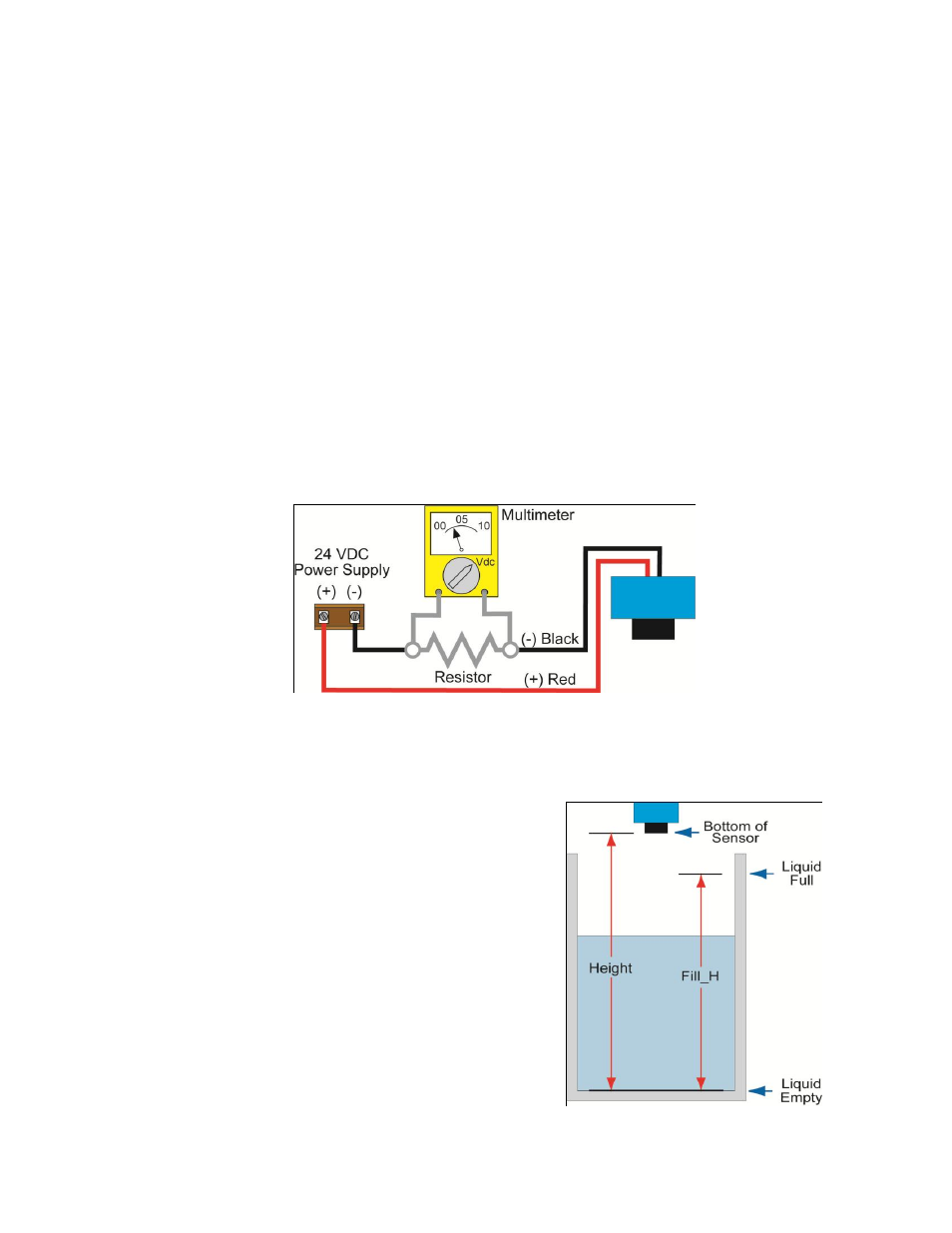
Voltage Output
EchoSpan can be used as a 0 to 5 or 0 to 10 VDC output device. A resistor will need to be added to
the circuit to enable a voltage output (refer to the wiring diagram below).
0-5 VDC output
o Add a 250 Ohm resistor
o Actual output will be 0.8 to 5 VDC
0-10 VDC output
o Add a 500 Ohm resistor
o Actual output will be 2 to 10 VDC
Getting Started:
EchoSpan can be configured before installation. The switch features non-volatile memory, so the set
points configured before installation will not be lost when the switch is powered down. To start, all
you need is the following information:
Basic Tank Information:
o HEIGHT – Distance from the transducer face to
the bottom of the tank.
o FILL-H – Maximum fill height of the liquid from
the bottom of the tank.
o These values will all be in the same distance
value (inches, centimeters, feet or meters) and
will all be measured from the bottom of the tank.
Power:
o Provide 12 to 28 VDC input power to the
EchoSpan.