Flowline LU29 EchoSonic II User Manual
Page 10
10
Wiring the EchoSonic® II
After mounting the sensor, make the necessary electrical connections. A wiring diagram
with specific recommendations for the sensor’s configuration can be printed from the
WebCal™ program. A typical wiring diagram is shown on the next page.
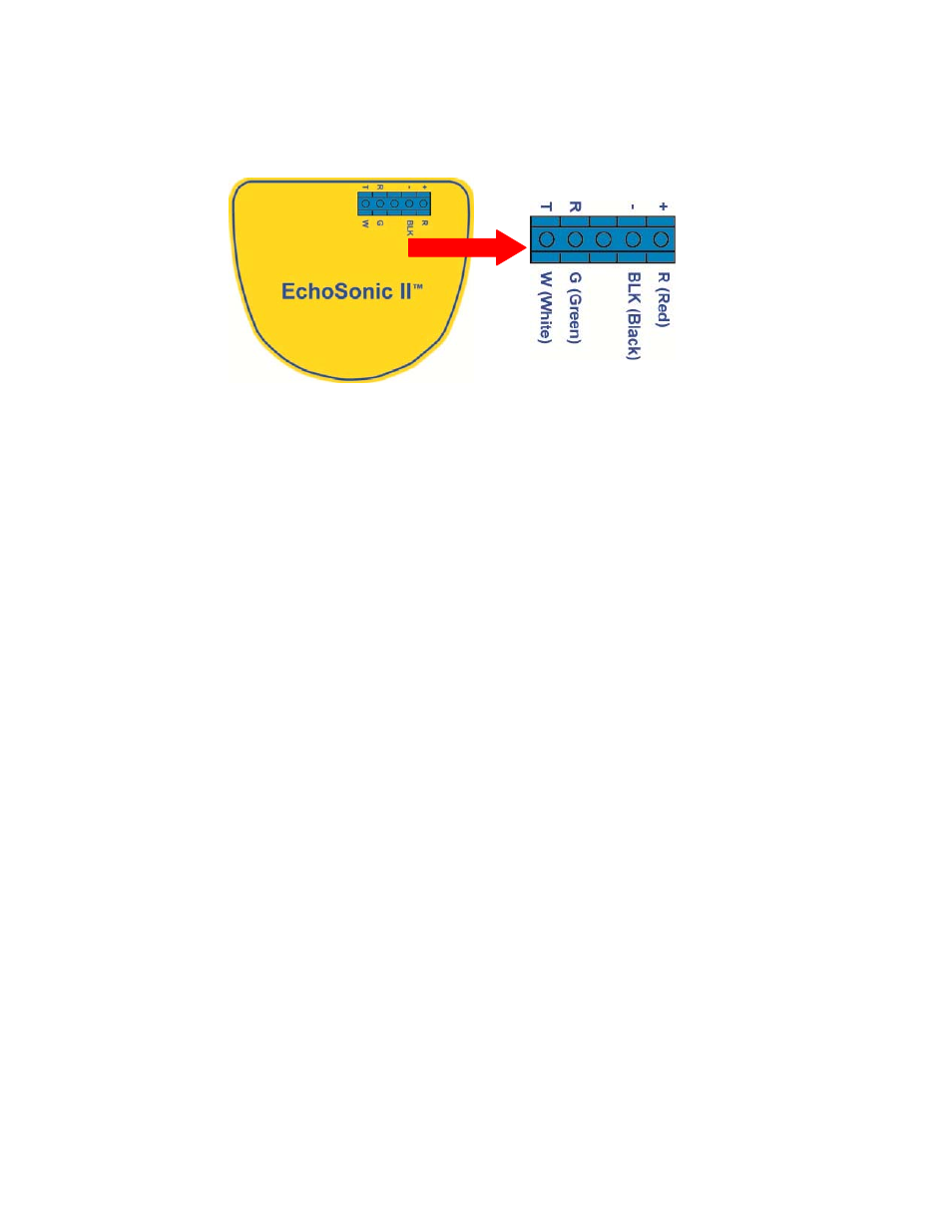
Red (+) & Black (‐): Red (R/+) and Black (BLK/‐) leads are for connection to a 24 VDC power
supply or to a 4‐20 mA loop power source. The red and black wires can be extended up to
1,000 feet using a 22 gauge or larger wire; however do not extend the green and white
wires.
White (T) & Green (R): White (W/T) and Green (G/R) leads are reserved for use with
WebCal™ and should not be connected during usage in the application. These wires should
not be connected to WebCal™ while power is supplied from any source other than the LI99
series Fob.
Never allow the white or green wires to touch any power supply.