Control and auxiliary equipment, Warning warning warning warning – Allstar Products Group CHALLENGER AC9300 User Manual
Page 12
12
D:
CONTROL AND AUXILIARY EQUIPMENT
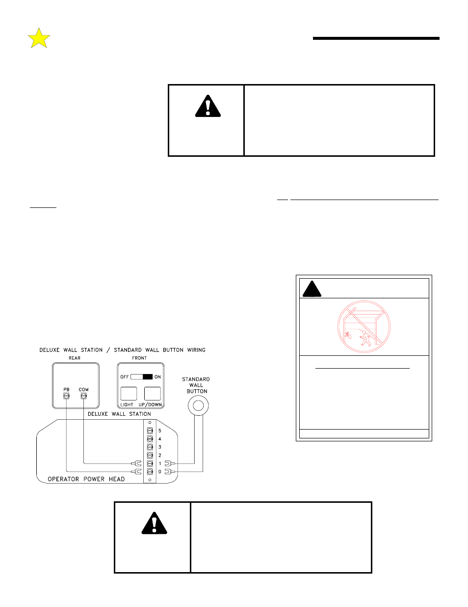
INSTALLATION OF A STANDARD WALL PUSH BUTTON OR DELUXE WALL STATION CONTROL
A standard wall push button is included
in your hardware package, an optional
Deluxe Wall Station may be purchased
from your installing dealer. The operat-
ing parameters for the standard wall
push button and the Deluxe Wall Station
are outlined on pages that follow
(“Operating Instructions”) to see what
mode of operation is right for you. All-
star recommends the Deluxe Wall Sta-
tion installation, as it will provide full
control over the garage door operator and its functions at all times. You may install one Deluxe Wall Station and one or more stan-
dard push buttons to a Challenger AC9000 Series operator following the cautions and instructions outlined below.
STEP 1:
After determining a suitable location, usually near the access door and at least 5 feet above the floor to prevent use by
children, use the standard wall push button or Deluxe Wall Station as a guide to mark the mounting holes. Drill holes for drywall
anchors or screws. NOTE: Do not mount directly to masonry walls. Use backer board.
STEP 2:
A length of 2-conductor, #22 gauge wire (or heavier) is required to connect the control button to the garage door operator.
Strip approximately 2” of the wire jacket from one end and 1/2” of insulation from each wire. Carefully connect one wire to each of
the two terminals. Carefully tuck the loose wires into the case and mount the unit using appropriate screws.
STEP 3:
Run the wire from the control button to the operator, supporting it at 18” intervals with suitable staples. Leave a
sufficient length to make the necessary connections to the operator terminal strip.
WARNING: SOME LOCAL BUILDING CODES DO NOT ALLOW
SURFACE WIRING. BE SAFE AND CHECK WITH YOUR LOCAL
BUILDING INSPECTOR FIRST.
STEP 4:
Ensure power is OFF to the operator or disconnect the power from the
operator. Strip approximately 4” of jacket from the end of the wire and 1/2”
insulation from each wire. Connect to terminals 0 and 1 as shown in the
illustration. Support the wire near the operator with wire ties.
Step 5:
Install the
Co ntr ol B utto n
W ar ni n g L ab el
supplied with your
Challenger AC9000
Series operator near
the control button
(see illustration).
Repeat the Steps 1
thru 5 above to in-
stall additional stan-
dard wall push but-
tons if desired.
Every control must
have a separate Con-
trol Button Warning
Label mounted near it. Contact the factory for additional labels if
needed.
WARNING
WARNING
WARNING
WARNING
A CHILD OPERATING THE DOOR CONTROLS
RISKS INJURY — OR DEATH — TO HIMSELF AND
OTHERS. DO NOT ALLOW CHILDREN TO
OPERATE
ANY
DOOR CONTROLS.
MOUNT THE PUSHBUTTON AT LEAST 5 FT FROM
THE FLOOR, OUT OF REACH OF CHILDREN.
!!!!
Child can be pinned under automatic garage
door. Death or serious injury can result.
• Never let child walk or run under moving door.
• Never let child use door opener controls.
• Always keep moving door in sight.
• If person is pinned, push control button or use
emergency release.
• Test door opener monthly:
Refer to your owner’s manual
Place one-inch object (or 2x4 laid flat) on floor.
If door fails to reverse on contact, adjust opener.
If opener still fails to reverse door, repair or replace opener.
WAR N I N G
104350
CONTROL BUTTON WARNING LABEL
WARNING
WARNING
WARNING
WARNING
IMPROPER DOOR OPERATION COULD
CAUSE INJURY OR DEATH. WARNING
LABEL MUST BE MOUNTED ON WALL NEAR
THE PUSHBUTTON. ALL WARNINGS AND
INSTRUCTIONS ON THE LABEL SHOULD BE
STRICTLY ADHERED TO.
109986