Electrical wiring – three phase, Warning, Epd / optima – EBARA EPD, Optima User Manual
Page 14: Ebara submersible sump/drainage pumps
EBARA
Fluid Handling
www.pumpsebara.com
16
(t) 803 327-5005 • (f) 803 327-5097
rev. 12/07
EBARA Submersible Sump/Drainage Pumps
EPD / Optima
Electrical Wiring – Three Phase
!
WARNING
Check that the power is locked off and disconnected before working on
pump. All electric work should be performed by a qualified electrician and all
national and local electrical codes must be observed.
NOTE:
Use with approved motor control that matches motor input in full load amperes with overload
element(s) selected or adjusted in accordance with control instructions.
Utiliser un d
é
marreur approuv
é
convenant au courant
á
pleine charge du moteur et dont les
é
l
é
ments thermiques sont r
é
gl
é
s ou choisis conform
é
ment aux instructions qui l’accompagnent.
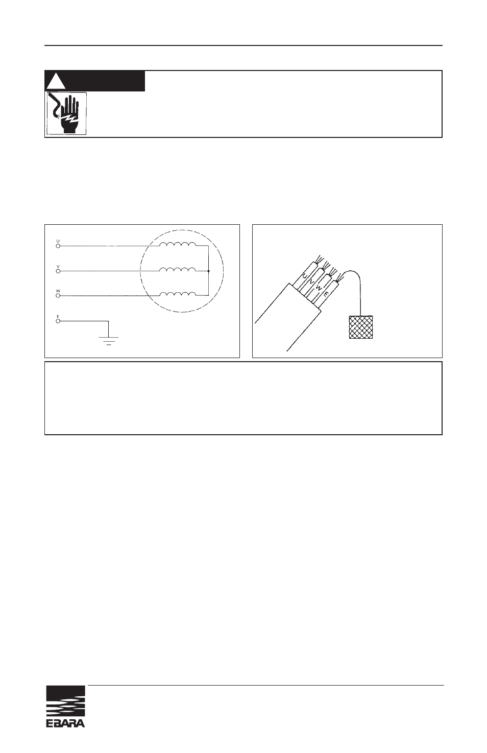
(1) Wiring
a) Wire as indicated for the appropriate start system as shown in Fig. 4
b) Loose connections will stop the pump. Make sure all electrical connections are secure.
MOTOR WIRING DIAGRAM
• Model P707U
• Output
1
/
2
to 1
1
/
2
HP
(2) Cable
a) Never let the end of the cable contact water.
b) If the cable is extended, do not immerse the splice in water.
c) Fasten the cable to the discharge piping with tape or vinyl strips.
d) Install the cable so that it will not overheat. Overheating is caused by coiling the
cable and exposing it to direct sunlight.
(3) Grounding
As shown in Fig. 5 ground the green/yellow wire (label E). Under no circumstances
should the green/yellow wire be connected to the power supply.
(4) Use short circuit breakers to prevent danger of electrical shock.
OPERATION
1. Before starting the pump:
(1) Check water level.
If the pump is operated continuously for an extended period of time in a dry condition
or at the lowest water level, the motor protector will be activated.Constant repetition of this
action will shorten pump service life. Do not start the pump again in such a situation until
after the motor has completely cooled.
(RED)
(BLACK)
(WHITE)
(GREEN/YELLOW)
Fig. 4
U phase: black
V phase: red
W phase: white
E phase: green/yellow
ground
plate
* Three phase only
Fig. 5