Part 2 - part 2 - transducer installation – Dynasonics 701_771C Series Insertion Ultrasonic Flow Meter User Manual
Page 16
Rev. 12/97 -15- D77X
PROBE INSERTION
Before beginning the probe insertion procedure, it is
necessary to calculate the probe insertion depth of the
sensor. For normal pipe runs, the probe tip must be
located at 1/8th of the pipe inside diameter. Figure 4
outlines the Necessary measurements and calculations
that will be needed to insure that the probe tip is at the
proper insertion point.
PART 2 -
PART 2 - TRANSDUCER INSTALLATION
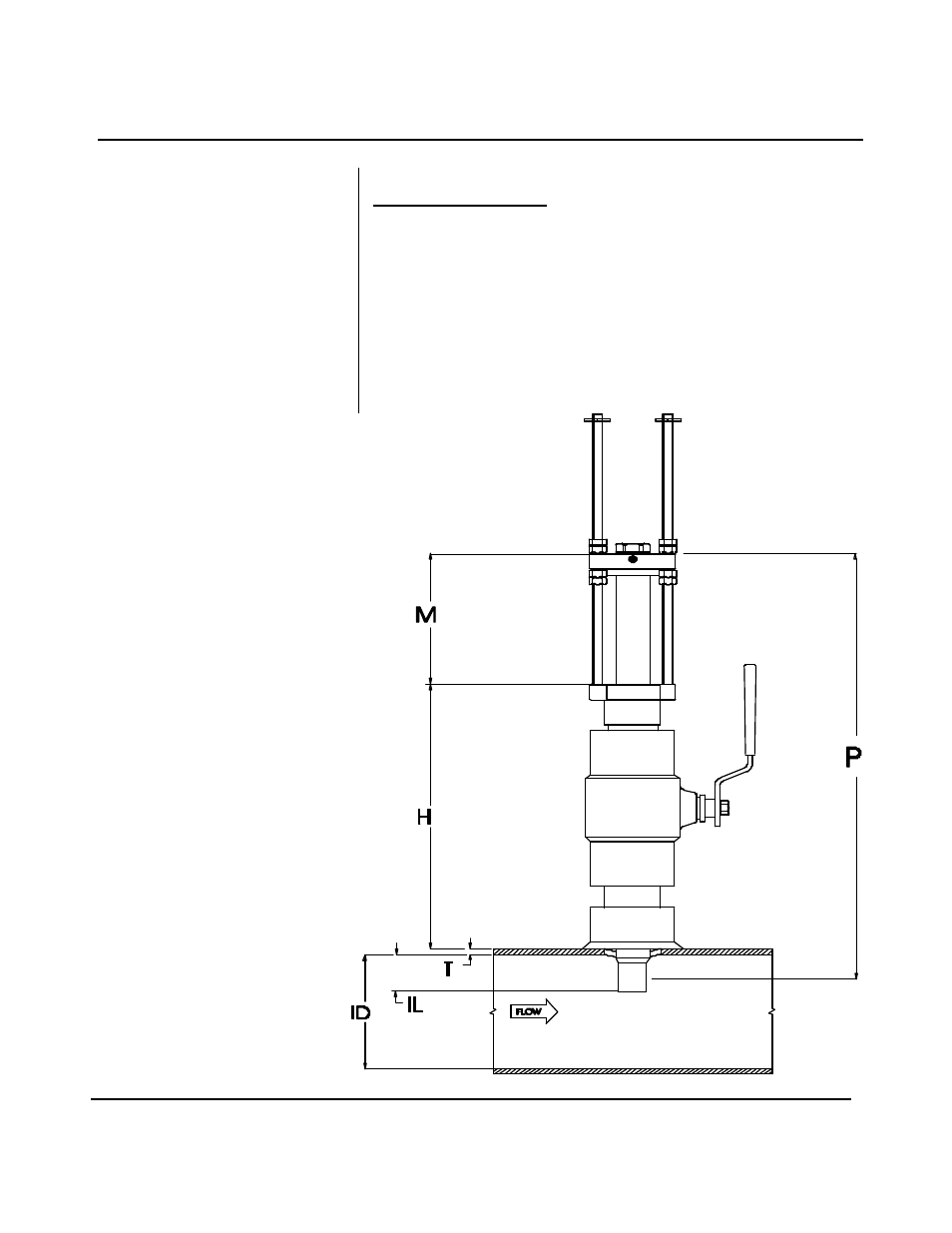
TO CALCULATE INSERTION DEPTH
P = PROBE LENGTH = _______
H = LOWER FLANGE TO PIPE WALL
= ________
T = PIPE WALL THICKNESS
= ________
IL = 0.125 x PIPE ID = ________
M = INSERTION DEPTH
M = P - IL - T - H - 0.67”
Figure 4
Step D - Probe
Insertion Distances