35
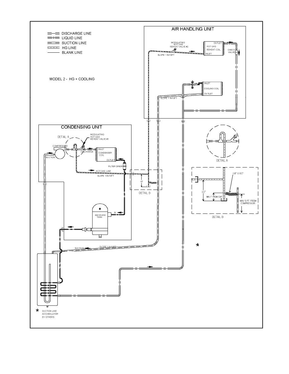
FIGURE RP-6. Hot Gas Reheat Piping Diagram with air handler above condenser and field installed
suction line accumulator.
Note: Components shown within air
handler and condensing unit are factory
installed; all other components are field
installed.
TO BE INSTALLED IN FIELD