Figure 10 - top view of module connection, Figure 11 - aligning two modules, Figure 12 - aligning the top of a unit – AAON M3-094 User Manual
Page 42: Figure 13 - lifting lugs and bolts, Figure 14 - come-along putting together modules
42
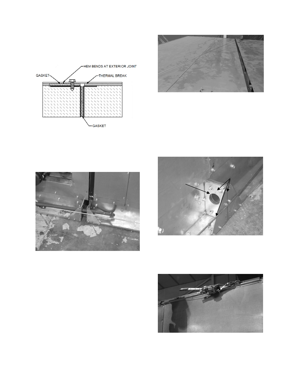
The following figure displays a top view of
the correctly overlapping module sections
with integrated splice.
Figure 10 - Top View of Module
Connection
A crow-bar or similar tool can be used
through the lifting holes to line up the two
sections.
Figure 11 - Aligning Two Modules
The top of the two sections can be aligned
by using a come-along diagonally across the
top of the unit.
Figure 12 - Aligning the Top of a Unit
5. Secure the two sections together with
bolts in the holes surrounding the lifting
hole in the base rail.
Be sure to replace the lifting lugs on either
side of the two base rails before bolting
together.
Figure 13 - Lifting Lugs and Bolts
6. Pull the top of the two sections together
using a come-along attached to the lug
points in the top-corner rail.
Figure 14 - Come-Along Putting Together
Modules
Bolts
Lifting
Lug