Variable capacity compressor controller, Warning – AAON RQ-006 User Manual
Page 70
70
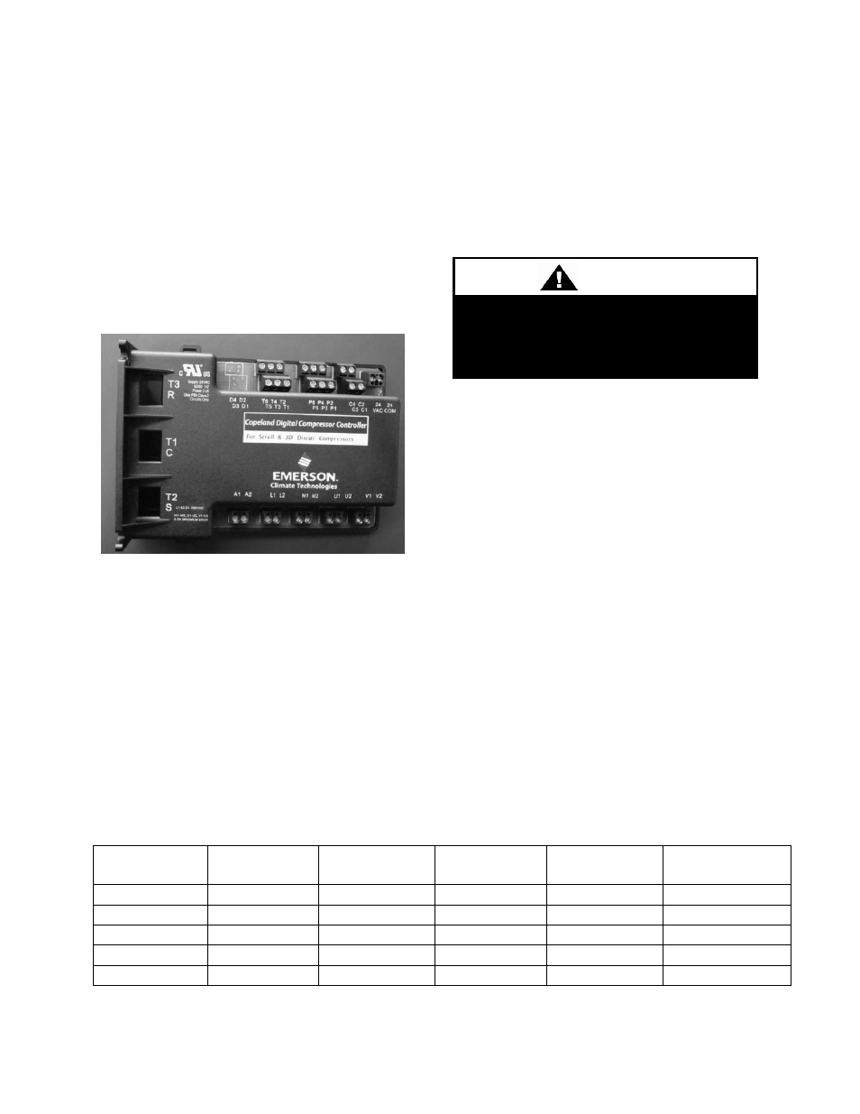
Variable Capacity Compressor
Controller
Units
with
variable
capacity
scroll
compressors may include the following
compressor controller. The following is an
explanation
of
the
terminals
and
troubleshooting alert flash codes of the
controller. For more information on the
compressor controller, see Emerson Climate
Bulletin AE8-1328.
Figure 35 - Variable Capacity Compressor
Controller
Low Voltage Terminals
24COM
Module Common
24VAC
Module Power
C1 & C2
Demand Input
P1
Pressure Common
P2
Pressure Input
P3
Pressure Power 5VDC
P4
Pressure Shield
P5 & P6
Pressure Output
T1 & T2
Discharge Temperature Sensor
High Voltage Terminals
A1 & A2
Alarm Relay Out
M1 & M2
Contractor
L1
Control Voltage N
L2
Control Voltage L
U1 & U2
Digital Unloader Solenoid
V1 & V2
Vapor Injection Solenoid
The compressor controller modulates the
compressor unloader solenoid in an on/off
pattern according to the capacity demand
signal of the system. The following table
shows the linear relationship between the
demand signal and compressor capacity
modulation. The compressor controller
protects the compressor against high
discharge temperature. Refer to Appendix B
for the relationship between thermistor
temperature readings and resistance values.
Table 17 - Demand Signal vs. Compressor Capacity Modulation
Demand
Signal (VDC)
Loaded %
Unloaded %
Time Loaded
Time
Unloaded
% Compressor
Capacity
1.00
Off
Off
Off
Off
0%
1.44
10%
90%
1.5 sec
13.5 sec
10%
3.00
50%
50%
7.5 sec
7.5 sec
50%
4.20
80%
20%
12 sec
3 sec
80%
5.00
100%
0%
15 sec
0 sec
100%
To avoid damaging the Compressor
Controller do not connect wires to
terminals C3, C4, T3, T4, T5, or T6.
WARNING