Phase and brownout protection, Figure 31 - 2-6 ton supply fan, Figure 32 - rq supply fan removal bolts – AAON RQ-006 User Manual
Page 68: Figure 33 - rq supply fan removal slide, Figure 34 - voltage monitor
68
Figure 31 - 2-6 ton Supply Fan
Remove wire connections from motor. For
EC motors unplug the wire harness at the
control module that connects to the unit
control panel.
Through the blower access opening, remove
the two 5/16” bolts that connect the blower
assembly to the inlet wall (see Figure 32).
Through the coil access door, remove the
two 5/16” bolts that connect the blower
assembly to the inlet wall from air entering
side of the wall (see Figure 32).
Figure 32 - RQ Supply Fan Removal Bolts
Slide blower assembly (wire frame motor
mount, motor, blower wheel, inlet, and
sheet-metal slide) out of unit through blower
access opening (see Figure 33).
Figure 33 - RQ Supply Fan Removal Slide
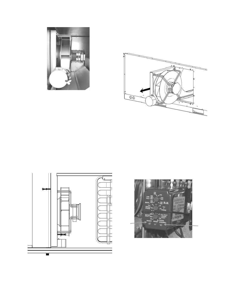
Phase and Brownout Protection
Voltage monitor should be wired according
to unit specific wiring diagram include in
the control compartment.
Before applying power to the unit the
voltage monitor should be set up. The three
knobs on the front of the monitor should be
adjusted.
Figure 34 - Voltage Monitor
Adjust the top knob labeled LINE VOLT to
the operating voltage. This should be the
operating voltage for the equipment and the
Phase
Loss/Rev.
LED
On/Off
LED