Supply fan ec motor startup – AAON RQ-006 User Manual
Page 58
58
Supply Fan EC Motor Startup
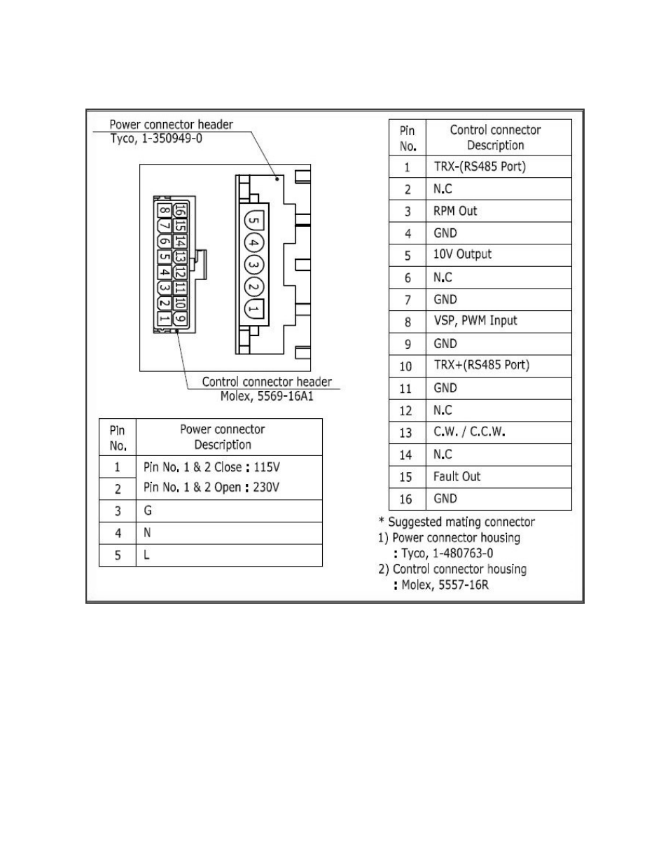
Figure 27 - PIN Connectors on EC Supply Fan Motor Electronics
Speed adjustment is made by varying the
DC voltage on pin 8 (+) & 16 (-). If
WattMaster, Mini Controller, or JENEsys
control systems are installed on the system
then they will provide the 0-10VDC signal
for speed control. The controller will be
wired directly to pin 8 & 16. If a
potentiometer is installed in the unit, the
10VDC output of the motor electronics will
be wired through the potentiometer and then
back into pin 8 & 16 for speed control. By
adjusting the potentiometer from 0-100%
you can manually adjust the speed of the
motor.
If the rotation direction is wrong, check the
brown wire on the control connector and
ensure that it is connected from pin 13 to pin
11. Making/Breaking this wire changes the
rotation of the motor.