Climacool – ClimaCool FLEX SERIES 30, 50, 65 User Manual
Page 28
ClimaCool
®
26
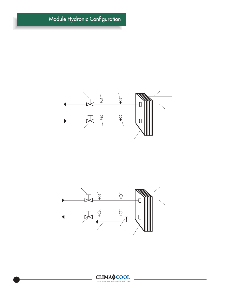
Figure 1 - Condenser Hydronic Circuit
Figure 2 - Chilled Water Circuit
NOTE: Figures 1 and 2 depict hydronic piping in each ClimaCool
®
chiller module.
Heat Exchanger
Refrigerant Circuit #1
Refrigerant Circuit #2
Service Port (3/4”)
Pete’s Port
Pete’s Port
Service Port (3/4”)
From Cooling Tower
To Cooling Tower
Header
Header
Isolation Ball Valve (2 or 2-1/2”)
Isolation Ball Valve (2 or 2-1/2”)
Heat Exchanger
Refrigerant Circuit #1
Refrigerant Circuit #2
Service Port (3/4”)
Pete’s Port
Service Port (3/4”)
Chilled Water Outlet
Chilled Water Inlet
Sensor Well (internal)
Cap Tube to Low Limit
Protection Thermostat
Header
Header
Isolation Ball Valve (2 or 2-1/2”)
Isolation Ball Valve (2 or 2-1/2”)
Pete’s Port
www.climacoolcorp.com
®