Assembling mount – CHIEF YAMF1 User Manual
Page 4
YAMF1
Installation Instructions
4
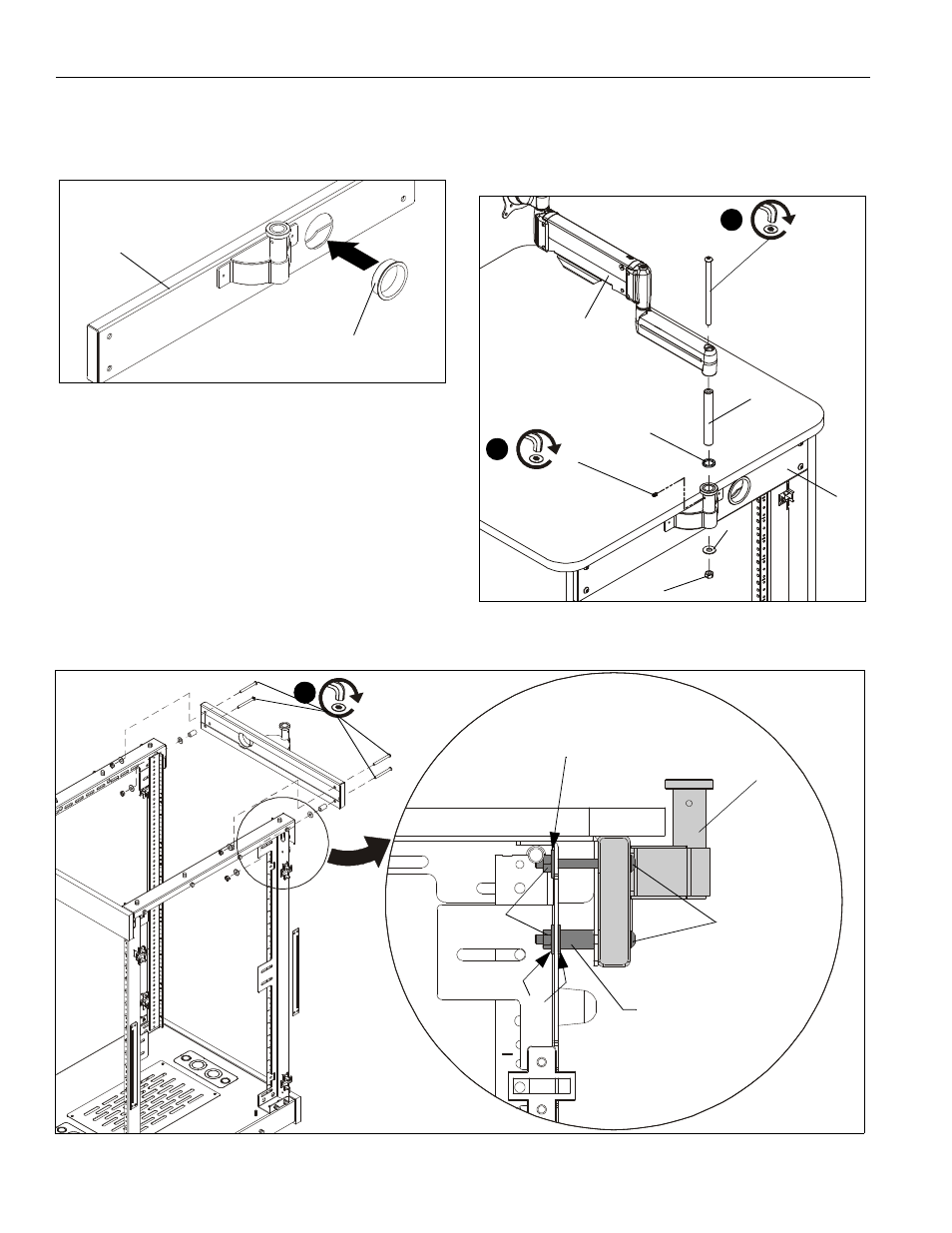
ASSEMBLING MOUNT
1.
Insert snap bushing (H) into F1 monitor mount (B). (See
Figure 1)
Figure 1
2.
Attach F1 monitor mount (B) to back of F1 rack using four
1/4-20 x 2-1/2" button head cap screws (F). (See Figure 1)
•
In each top hole, also use a 1/4" washer (J) and a
1/4" nut (L).
•
In each lower hole, also use two 1/4" washers (J),
one spacer (E) and a 1/4" nut (L). (See Figure 3)
IMPORTANT ! : If installing a display with RECESSED
mounting holes, proceed to Installing Display section
before continuing with this mount installation procedure.
3.
Attach F1 mount arm with head assembly (A) to F1 monitor
mount (B) using one 5/16-18 x 5-1/2" button head cap screw
(G), the monitor mount pin (C), one nylon spacer (D), one
5/16" washer (K) and one 5/16" nut (M). (See Figure 2)
4.
Insert and tighten one 10-32 x 3/8" set screw (N) into
monitor mount (B). (See Figure 2)
Figure 2
(H)
(B)
3
(G) x 1
(A)
(D)
(C)
(K)
(M)
(B)
4
(N) x 1
Figure 3
(F) x 4
(F)
(B)
(E)
(L)
(J)
(J)
2
- PACPC1 (8 pages)
- CMS Series Columns (8 pages)
- CPA Series Columns (4 pages)
- PAC390 (2 pages)
- KTA1005 Series (8 pages)
- KFA225 Series (12 pages)
- PAC391B (8 pages)
- KTA1007 Series (4 pages)
- KSA1024B (8 pages)
- PAC392B (8 pages)
- KTP Series (8 pages)
- KSA1011 (8 pages)
- FSA1015 (8 pages)
- OFB214 (4 pages)
- KTA220_225 (8 pages)
- KSA1021 (8 pages)
- KSA1022 (16 pages)
- KSA1250 (8 pages)
- KSA1250 (16 pages)
- KRA500 (4 pages)
- PAC261 Series (12 pages)
- KSA1023 (12 pages)
- KSA1020 (12 pages)
- FSA1001 (1 page)
- FSA1002 (2 pages)
- FSA1003 (1 page)
- FSA1005 (1 page)
- PAC200 (6 pages)
- MAC722 (8 pages)
- FSA1009 (8 pages)
- FSA1008 (1 page)
- PAC720 (6 pages)
- KSA1018 (8 pages)
- KSA1012 (1 page)
- MAC720 (6 pages)
- KTA1000 (4 pages)
- FSA1013 (8 pages)
- KTA1001 (8 pages)
- KSA1014 (6 pages)
- KSA1017 (8 pages)
- KTA1003 (6 pages)
- KSA1019 (8 pages)
- KTA1004 (8 pages)
- PAC775 (4 pages)
- PAC790 (8 pages)