CHIEF PSBU User Manual
Page 6
PSBU
Installation Instructions
6
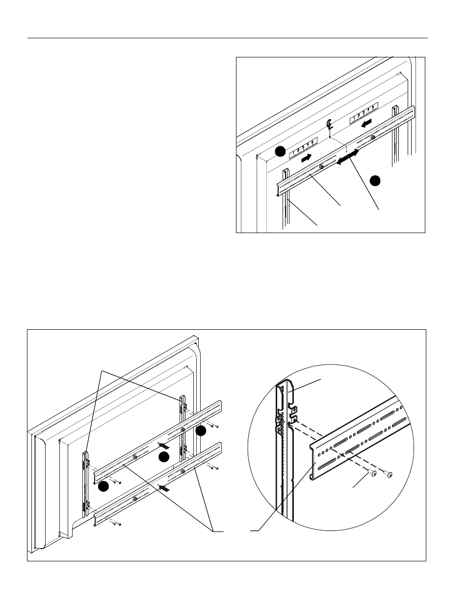
9.
Determine and mark the horizontal center position between
the Left and Right TOP mounting holes in display.
(See Figure 3)
10. Determine and mark the horizontal center position between
the Left and Right BOTTOM mounting holes in display. (See
Figure 3)
11. Orient upper horizontal mounting bracket (U) so that flanges
are facing towards display and resting in recessed area of
left and right vertical mounting brackets (T). (See Figure 3)
12. Adjust Upper horizontal mounting bracket (U) position until
center diamond in horizontal mounting bracket (U) aligns
with mark made in Step 9, and mounting holes and slots in
horizontal mounting bracket (U) are aligned with threaded
holes in mounting tabs of left and right vertical mounting
brackets (T). (See Figure 3) and (See Figure 4)
13. Use 1/8" hex key (V) to secure upper horizontal mounting
bracket (U) to left and right vertical mounting brackets (T)
using four button head flanged screws (A). (See Figure 4)
14. Repeat Steps 10 through 13 for lower horizontal mounting
bracket (U).
IMPORTANT ! :
The orientation of, and mounting holes used,
when installing the lower horizontal mounting bracket must be
the same as the upper horizontal mounting bracket. Vertically
align upper and lower brackets by aligning holes or end of slots.
(See Figure 4)
IMPORTANT ! : Whenever possible install mounting
screws diagonally as shown in detail in Figure 4 below.
15. Install display with attached universal interface to mount
following the installation instructions provided with the
mount.
Figure 3
10
9
(T) x 2
Center Mark
(U) x 2
Figure 4
13
13
(U) x 2
(T) x 2
(A) x 8
(T) x 2
12