CHIEF KFA320 Series User Manual
Page 9
Installation Instructions
KFA SERIES
9
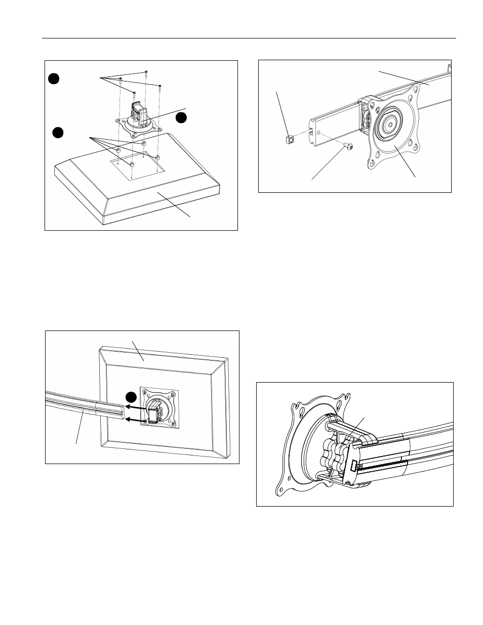
Figure 8
7.
Slide display with Centris bracket onto mounting rail.
(See Figure 9)
NOTE: Repeat previous steps for each additional display.
8.
Install end locks into mounting rail using the 5/32" hex
key (H). (See Figure 10)
Figure 9
Figure 10
Display Adjustment
These pivot arrays allow horizontal, pitch, roll, and yaw
adjustment of each display with a maximum pitch range
of 15° up and 15° down.
These pivot arrays also allow a full 360 deg. of display
roll.
Display Horizontal Position Adjustment
To adjust display horizontal position:
1.
Loosen Centris bracket rear adjustment knob.
(See Figure 11)
2.
Slide Centris bracket with display left or right until
properly positioned on array rail.
3.
Tighten Centris bracket rear adjustment knob.
Figure 11
Display Pitch, Roll, and Yaw Adjustment
To adjust display position:
1.
Loosen Centris bracket front adjustment knob.
(See Figure 12)
2.
Tilt display up or down, or adjust display roll left or
Display
Centris Head
(G or D) x 4
(E or F) x 4
4
5
6
Display with Centris Bracket
Array Rail
7
End Lock
End Lock Retaining Screw
Centris Head
Array Rail
rear adjustment knob