Assembly and installation – CHIEF KTA1005 Series User Manual
Page 4
KTA1005
Installation Instructions
4
ASSEMBLY and INSTALLATION
The following procedure assumes a base and pole have been
purchased and are available. The procedure also assumes that
no displays are mounted to the array.
1.
Assemble pole and base following instructions included with
those kits.
2.
Slide display with Centris bracket onto mounting rail.
(See Figure 1)
Figure 1
3.
Install end locks into mounting rail. (See Figure 1)
4.
Tighten inner knob to tighten array head to mounting rail.
5.
Determine mounting pattern on display.
WARNING:
IMPROPER INSTALLATION CAN LEAD TO
EQUIPMENT FALLING CAUSING SERIOUS PERSONAL
INJURY AND DAMAGE TO EQUIPMENT! DO NOT
substitute hardware. Use only hardware supplied by
manufacturer!
WARNING:
IMPROPER INSTALLATION CAN LEAD TO
ELECTRIC SHOCK OR DAMAGE TO EQUIPMENT! Screw
length must not exceed the depth of threaded mounting insert
in display.
WARNING:
IMPROPER INSTALLATION CAN LEAD TO
DISPLAY FALLING CAUSING SERIOUS PERSONAL
INJURY OR DAMAGE TO EQUIPMENT! Using screws of
improper size may damage your display! Proper screws will
easily and completely thread into display mounting holes.
Ensure that screws are not too long.
WARNING:
IMPROPER INSTALLATION CAN LEAD TO
DISPLAY FALLING CAUSING SERIOUS PERSONAL
INJURY OR DAMAGE TO EQUIPMENT! Inadequate thread
engagement in display may cause display to fall! Back out
screws ONLY as necessary to allow installation of mounting
plate!
WARNING:
IMPROPER INSTALLATION CAN LEAD TO
DISPLAY FALLING CAUSING SERIOUS PERSONAL
INJURY OR DAMAGE TO EQUIPMENT! Support and
arrange existing monitors or devices along with those being
installed to ensure an overall balanced weight distribution.
This is especially important in free-standing units.
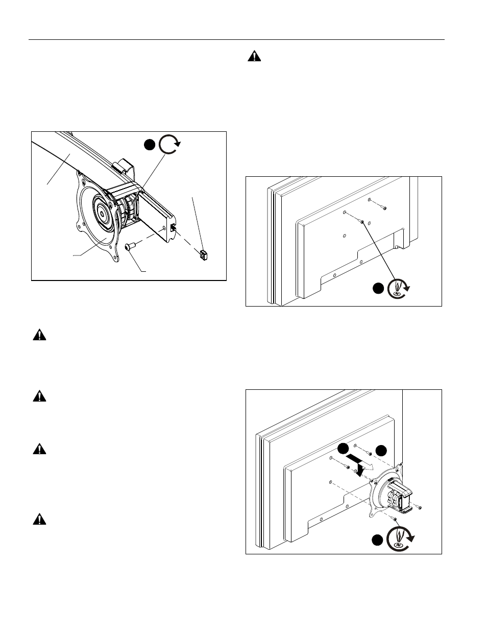
Display Installation - Flush Mount Display
1.
Start two M4 x 12mm Phillips pan head screws (B) into
upper mounting holes in display back. (See Figure 2)
NOTE:
Leave at least 1/8" of each screw protruding out back
of display.
Figure 2
2.
Align two screws in display back with upper teardrop
mounting holes in KTA-1005.
3.
Place two screws in display back into upper teardrop
mounting holes in KTA-1005 and lower display until screws
are seated in lower area of teardrop mounting holes.
(See Figure 3)
4.
Install two screws through display mounting plate and into
lower mounting holes in display back. (See Figure 3)
Figure 3
5.
Tighten all hardware.
Array
End Lock
Square Nut
KTA-1005
Tighten to
mounting rail
4
(B) x 2
1
2
3
4
(B) x 2