Adjustments – CHIEF PCM Series User Manual
Page 6
PCM Series
Installation Instructions
6
NOTE:
Holes are provided in the faceplate for use with a
padlock or similar locking device, if desired. In addition,
the pin and nut may be removed from the upper holes
and moved to the lower holes for use as a more
permanent locking device. (See Figure 4)
Figure 4
Adjustments
The PCM is designed to accommodate 5" of display height
adjustment, 4º right and left display roll adjustment, and 15º
down/5º up display pitch (Tilt) adjustment.
Remove display before performing adjustments.
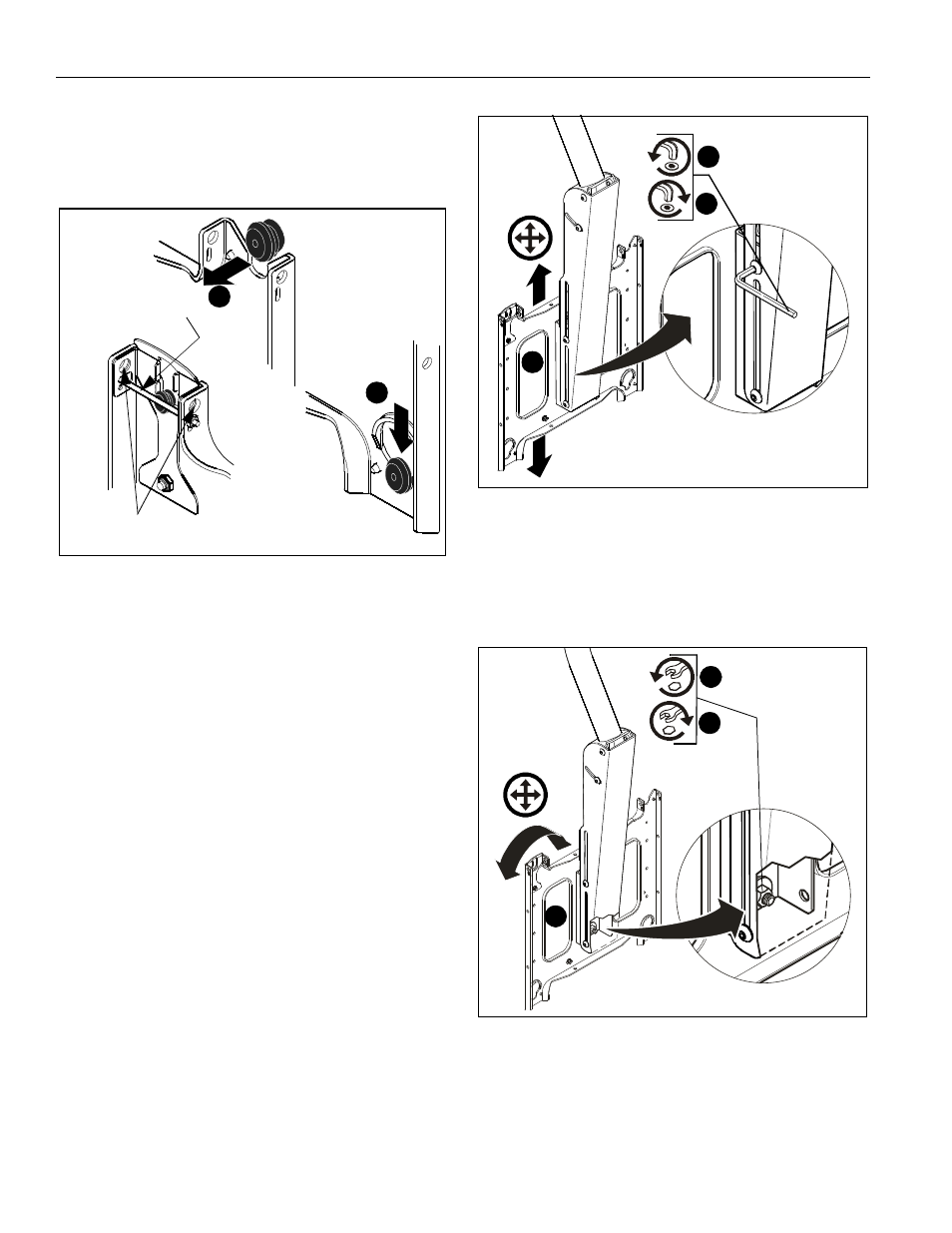
Display Height Adjustment
To adjust display height:
1.
Loosen four 5/16-18 button head cap screws using 3/16”
hex wrench (C). (See Figure 5)
2.
Adjust faceplate to desired position. (See Figure 5)
3.
Tighten four 5/16-18 button head cap screws using 3/16”
hex wrench (C). (See Figure 5)
Figure 5
Display Roll Adjustment
To adjust display roll:
1.
Loosen 3/8-16 Nylock nut. (See Figure 6)
2.
Adjust faceplate to desired position. (See Figure 6)
3.
Tighten 3/8-16 Nylock nut. (See Figure 6)
Figure 6
2
1
A padlock or bolt may
be placed through latch holes
To use as a
more permanent
lock, remove pin
and nuts and move
to lower holes
3
1
2
3
1
2