Installation – CHIEF MWRIW Series User Manual
Page 6
MWRIW Series
Installation Instructions
6
Installation
The following procedure assumes that a Chief Listed Model
PAC501 In-Wall accessory has previously been installed
following the installation instructions provided with the PAC501.
If a PAC501 is not installed or there are any other questions
regarding the installation of this accessory, immediately contact
a Chief Customer Service representative.
WARNING:
IMPROPER INSTALLATION CAN LEAD TO
MOUNT FALLING CAUSING SEVERE PERSONAL INJURY
OR DAMAGE TO EQUIPMENT! DO NOT deviate from
installation instructions provided. DO NOT substitute
hardware.
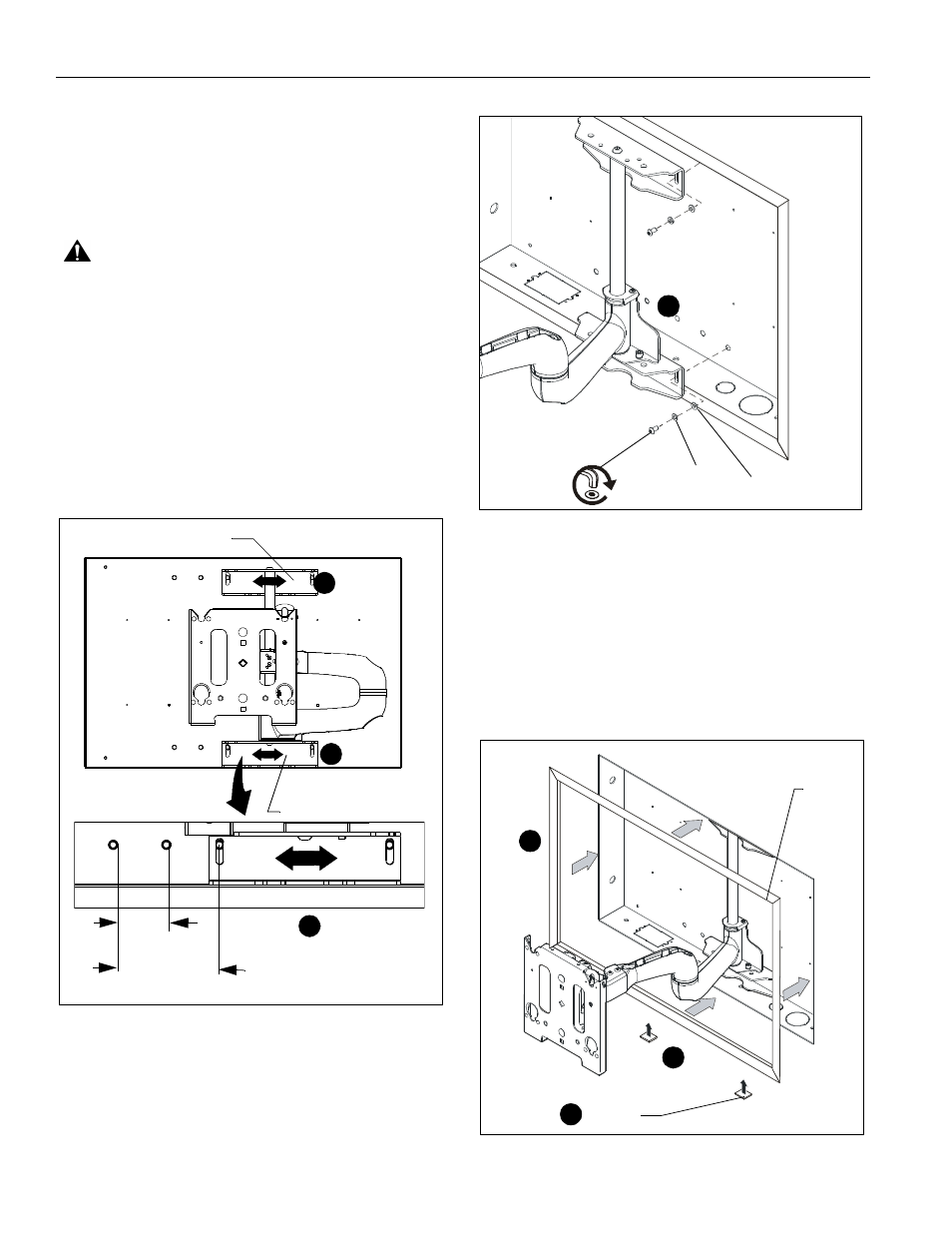
The PAC501 is designed to accommodate up to 5" of right or
left display offset. This is accomplished by aligning the upper
and lower mounting brackets on the MWRIW with either the
right hand or left hand mounting holes in the PAC501. (See
Figure 1)
1.
Align mounting holes in swing arm UPPER and LOWER
mounting brackets with four mounting holes in PAC501.
(See Figure 1)
Figure 1
2.
Secure swing arm to PAC501 using four button head cap
screws (C), four lock washers (D) and four flat washers (E).
(See Figure 2)
Figure 2
Trim Installation
To install optional trim;
1.
Remove paper covering adhesive and affix three tape
squares (F) to inside lower flange of each trim piece (B).
(See Figure 3)
2.
Orient trim pieces (B) as shown in figure below.
(See Figure 3)
3.
Remove paper covering adhesive back from tape squares
(F) on trim and press trim (B) against inner wall of box.
(See Figure 3)
Figure 3
1
1
1
5"
Upper Mounting Bracket
Lower Mounting Bracket
(Display Offset Left)
(Display Offset Right)
2-1/2"
(C) x 4
(E) x 4
(D) x 4
2
(F) x 12
1
(B) x 4
3
2