Assembly to desk – CHIEF STLU User Manual
Page 6
STLU
Installation Instructions
6
Assembly to Desk
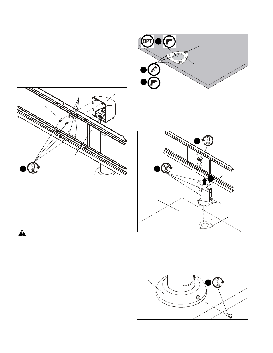
1.
Use four 1/4-20 x 1/2" button head cap screws (H) to secure
table stand (B) to table stand interface (C). (See Figure 1)
NOTE:
If roll adjustment is desired, install through screws
through rotational slots rather than the standard slots.
(See Figure 1)
NOTE:
In order to achieve a +/- 90 rotation radius while using
the rotational slots, the rotational stop adjustment
screw must be removed and replaced with #10-24 x
1/2" socket head cap screw (M). (See Figure 1)
Figure 1
2.
Determine mounting location by setting table stand on desk
and experimenting with desired rotation capabilities.
NOTE:
Rotation radius can be set to be either +/- 15 , 30 , 45 ,
or 90 . See Dimensions graphic for details.
3.
Use clamping plate (A) as a template to mark locations for
the three holes to be drilled at desired mounting location.
WARNING:
Failure to provide adequate structural strength
for this component can result in serious personal injury or
damage to equipment! The mounting surface must be a
minimum of 3/4" in depth for medium-density fibreboard or
particle board. If mounting to another type of surface, make
sure surface can hold up to four times the combined weight of
all equipment prior to mounting the STLU to surface!
4.
Drill three 5/16" holes at locations marked in Step 3. (See
Figure 2)
NOTE:
If cables are going to be routed through the table, an
additional hole needs to be drilled in center of clamping
plate (A). See Cable Management Section for details.
5.
(Optional) If cables are going to be routed through the desk,
drill an additional hole in the center of the clamping plate
that is large enough to account for all cables that will be
routed through the desk. (See Figure 2)
NOTE:
One hole should be centered at the front of the mount.
Figure 2
6.
Lift lower cover on table stand to expose holes on lower
plate. (See Figure 3)
7.
Use three 1/4-20 x 2 1/2" hex head cap screws (G) and
three 3/16" washers (L) to secure table stand (B) to desk
and clamping plate (A). (See Figure 3)
Figure 3
IMPORTANT ! :
Provided screws (G) can be used to install
on surfaces up to 1 5/8" in depth. For deeper tables, longer 1/4-
20" screws that are not provided must be used.
8.
Secure lower cover to table stand (B) using #10-24 x 1/2"
security screw (K). (See Figure 4)
Figure 4
1
(B)
(C)
(H) x 4
rotational slots
stop adjustment
screw
rotational
x 3
front of mount
3
4
x 3
5
(A)
lower cover
(G) x 3
6
(L) x 3
(A)
desk
stop adjustment
screw
7
9
rotational
(K)
8
(B)