CEMB USA K8 (A) User Manual
Page 5
I 0369 -
4
I 0369 -
5
������
��
��
����
3
3a
GB
GB
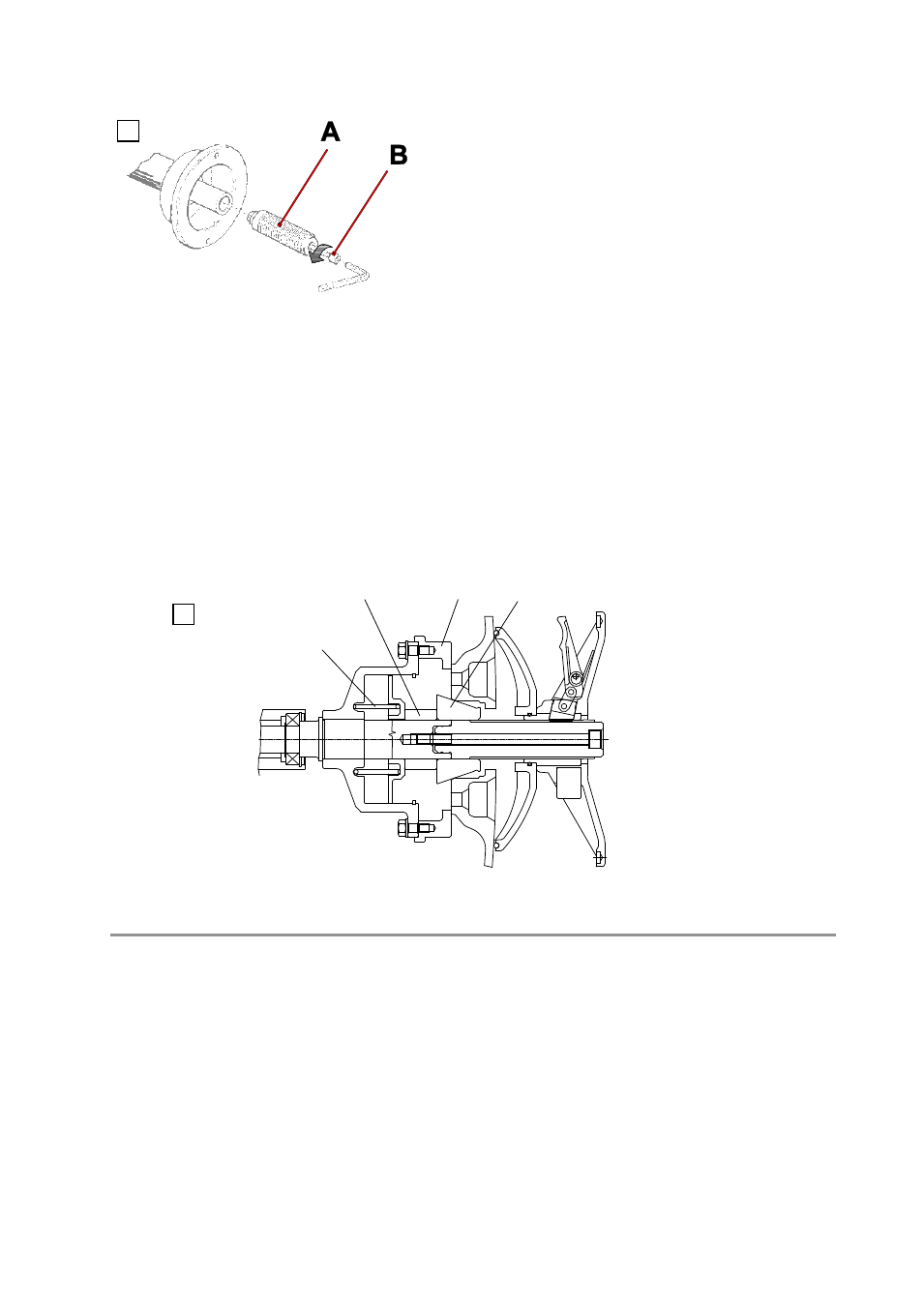
3.3 - Flange mounting
4 - Controls and components
4.1 - Manual distance measurement gauge
This gauge serves to manually measure the distance between the point of application of the counterweight and the
machine.
The wheel balancer is supplied complete with cone
flanges
for fixing wheels with a central hole. Other optional
flanges can be mounted:
a) Remove the threaded end-piece A after unscrewing
the screw B.
b) Mount the new flange (see attached sheets).
Note: CAREFULLY CLEAN THE COUPLING
SURFACES BEFORE PERFORMING ANY
OPERATION.
3.4 - Wheel guard assembly and adjustment (optional)
Fix the components to the base as described in the attachment
“WHEEL GUARD ASSEMBLY SEQUENCE” at
the end of the manual.
N.B.: Do not lean on the guard during the wheel balancing cycle.
3.5 - WD spacer (option)
When balancing very wide wheels (9”), there is not enough space to turn the distance gauge. To move the wheel
away from the machine side, fit the WD spacer on the flange body and secure it with the standard issue nuts. When
centring the wheel with cone from the inside, mount the DC spacer to obtain spring thrust.