Battery, Figure 4.2 – J&M 375ST User Manual
Page 35
32
3.0 Hydraulics
4.0 Wiring
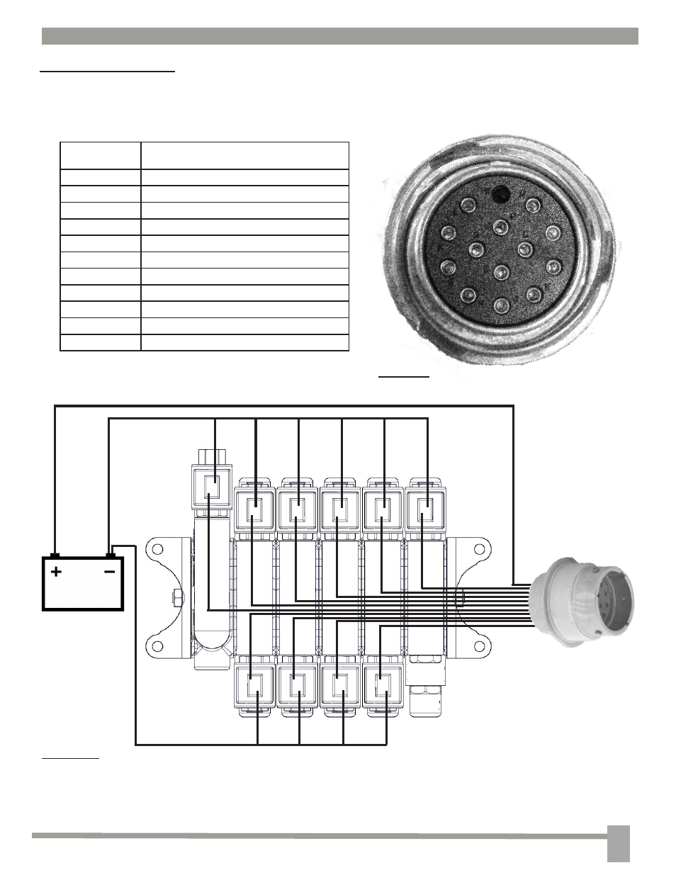
4.1 Hydraulic Wiring
To Figure 4.1
NOTE: Figure 4.2 is a 5 spool valve body. For the 4 spool valve body ignore the Conveyer/Auger swing
bank. For the 2 spool valve body, ignore the Conveyer/Auger swing, and the front and rear door banks.
NOTE: The 2 spool valve body uses a 4 pin weather pack in place of the connectors above (Figure 4.1).
In/Out from pump
Conveyer/Auger
Motor
Rear Door
Conveyer/Auger
Up/Down
Conveyer/Auger
Swing
Front Door
Battery
J
M
N
Reference
Figures 4.1-4.4
Function
C
Boom swing front (optional)
D
Boom swing rear (optional)
E
Boom Up
F
Boom Down
G
Rear door up (optional)
H
Front door down (optional)
J
Power
K
Front door up (optional)
L
Rear door down (optional)
M
Pump In
N
Conveyor Start
P
F
A
B
J
H
G
E
L
N
K
M
C
D
Wireless Reciever
or Handheld Controller
Connector
Figure 4.1
Figure 4.2
G
K
E
F
L
H
C
D
- 525-14W (31 pages)
- 750-16 (33 pages)
- 750-18 (34 pages)
- 1000-20 (31 pages)
- 1050-20 (37 pages)
- 1130-20 (36 pages)
- 1325-20 (36 pages)
- GC-24T Manual (39 pages)
- GC-31T Manual (38 pages)
- GRAIN CARTS Leaner Setup (18 pages)
- 250-7S (12 pages)
- 385SD (13 pages)
- 440SD (13 pages)
- 680SD (13 pages)
- 750SD (13 pages)
- GW15t-1 (20 pages)
- 275ST (62 pages)
- 500ST (51 pages)
- 375ST Remote (24 pages)
- 500ST Remote (23 pages)
- PRO 450 (31 pages)
- TF2 (37 pages)
- HT-974 (16 pages)
- TB-3500-6000A (20 pages)
- TB-3500-6000H (21 pages)
- TB-8000H-42 (20 pages)
- 4WS15 (27 pages)
- 750-14 (29 pages)
- 818 (35 pages)
- 875-16 (29 pages)
- 1000-20S (34 pages)
- 1050-18S (28 pages)
- 1050-18D (22 pages)
- 1050-20S (33 pages)
- 1050-20D (33 pages)
- 1050-22S (23 pages)
- 1050-22D (14 pages)
- 1051-22S (33 pages)
- 1051-22D (33 pages)
- 1075-18R (23 pages)
- 1075-22R (23 pages)
- 1325-20S (33 pages)
- 1325-20D (33 pages)
- 1325-22S (23 pages)