J&M GC-24T Manual User Manual
Page 22
21
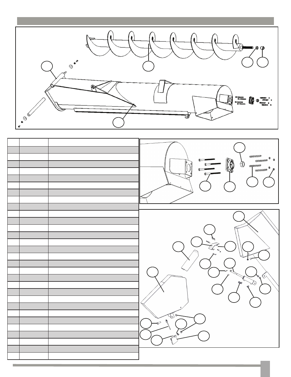
UPPER AUGER ASSEMBLY
#
Part. No. Description
1
JM0001881
Upper Auger Light Assembly
2
JM0000100
M10 x 20 Hex Head Bolt
3
JM0002162
M10 Nylon Lock Nut
4
JM0000102
Loom
5
JM0017896
Mercury Switch
6
JM0000104
Flow Control Spout Housing
7
JM0000105
Baffle Plate
8
JM0010301
1/4” Swivel Connector
9
JM0010303
1/4” St. Elbow
10
JM0018264
1/2” x 1 1/2” Clevis Pin
11
JM0003064
Cotter Pin
12
JM0018564
Hydraulic Cylinder with Clevis End
13
JM0001490
M12 x 50 Hex Head Bolt
14
JM0002163
M12 Nylon Lock Nut
15
JM0001490
M12 x 50 Hex Head Bolt
16
JM0001511
M12 Nylon Lock Nut
17
JM0002167
8.8M6 Nut
18
JM0019447
8.8M6 Flat Washer
19
JM0000117
Upper Auger Housing 18”
20
JM0018432
Hinge Plate
21
JM0002120
8.8M6 x 20MM Bolt
22
JM0001498
1/2” x 5 1/2” Bolt
23
JM0018560
1 1/4” Flange Bearing, 4 Hole
24
JM0018559
Compression Spring
25
JM0001511
1/2” Centerlock Hex Nut
26
JM0001700
1 1/4” Hex Nut
27
JM0009756
Grease Zerk
28
JM0000130
Upper Flighting
29
JM0016920
1 1/4” Jam Nut
30
JM0016792
1 1/2” Long Spacer
23
2
24
3
25
4
26
5
27
6
28
7
29
8
30
9
1
15
16
17
18
19
20
21
22
10
11
12
13
14
2
19