Adcom GTP-760 User Manual
Page 13
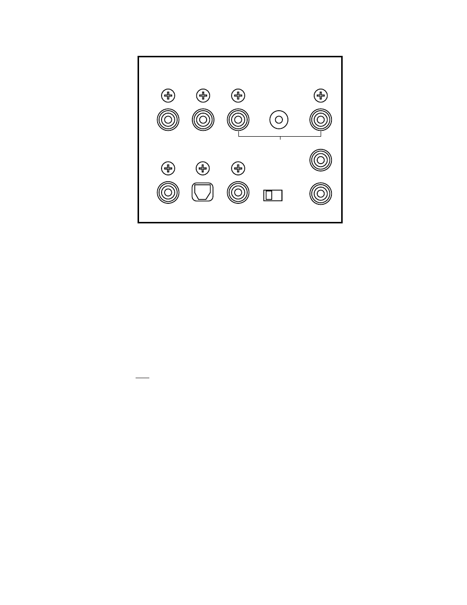
Video) to the appropriate “dig.2 in” jack.
Digital 2 in: This input is recommended for an audio/video source (DSS receiver, etc.) with a
TOSlink (optical) digital output.
Remember that the composite video connection will go to the yellow-center RCA jack
immediately under the “dig.2 in” label.
Connect the source’s TOSlink (optical) digital output to the GTP-760’s TOSlink socket located
under the “dig.2 in” label.
Digital 1 in (RF): We recommend this input for laserdisc players with a digital RF output.
It is the only input on the GTP-760 equipped with the RF demodulator needed to process a
laserdisc’s Dolby Digital encoded soundtrack.
Connections follow the same pattern detailed in “DVD in” and “Dig.2 in” above. Connect the
laserdisc player’s composite video output to the yellow-center RCA jack immediately under the
“dig.1” label. Then connect the player’s coaxial digital output to the black-center RCA jack
under the “dig.1 in” label.
20
Digital 1 RF Demodulator (bypass) Switch
(see illustration on preceding page)
This switch adds flexibility to the GTP-760. If you play laserdiscs with Dolby Digital-encoded
soundtracks, put this switch in the IN position. This places the demodulator circuit in the signal
path and allows proper Dolby Digital decoding.
If you do not have a laserdisc player with a digital RF output, place the switch in the OUT
position. You can then use this input in exactly the same way as you would use the DVD input.
D V D
i n
i n
i n
d i g i t a l 2
d i g i t a l 1
D V D
i n
i n
i n
i n
o u t
d i g i t a l 2
d i g i t a l 1
d i g 1 R F
d e m o d u l a t o r
S t a n d a r d
v i d e o
i n
L D
1 2 V
t r i g g e r o u t
L
R
i n
12