Model tp-3 service – PA Industries Transporter User Manual
Page 6
6
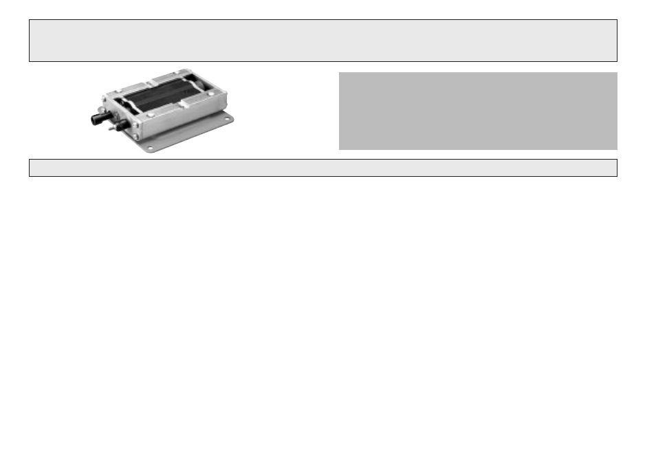
1. Remove both Snap Rings and push the Front and
Rear Pistons inside Body.
2. Remove the Screws from the Rear Guide Holder
T3-204. Pull out together with Speed Adjustment
Knob T3-401.
3. Remove the Front Guide Holder T3-203.
4. Remove both Guide Holders (L & R) T3-201 and the
twelve (12) Ball Bearings.
5. Back out the Locking Screw T3-406 and remove the
Speed Adjustment Valve T3-603.
6. With both T3-701 Tools provided in the kit, remove the
Valve Discs and the Rod.
7. Check all “O” Rings, Springs, Discs, and Seals for
damage and replace as needed.
Factory Repair & Rebuild Service
Return the Transporter by UPS Prepaid to our repair center.
After teardown and inspection, P/A Industries will notify you
of the recommended cost for spare parts and labor.
1. Install the Speed Adjustment Valve T3-603 and align
with the groove for the Locking Screw T3-406.
2. Insert the Front Piston T3-302 into the Body with the
Bumper Ring.
3. Mount the Bumper Ring and insert the Rear Piston
T3-303 into the Body.
4. Grease both Guide Holders T3-201 and put twelve (12)
Ball Bearings into both Bearing Plates T3-210. Hold
the Bearing Plates by hand while attaching Front and
Rear Holders. The Guide Holder assembly must run
smoothly in both directions without side-to-side
play.
5. Pull both Pistons T3-302 and T3-303 back into position
and secure the Snap Rings.
MODEL TP-3 SERVICE
Disassembly
Reassembly