5 threading the tool – PA Industries Magnum Servo Roll Feed SRF-M12/18/24/32/36/48 - Installation Manual User Manual
Page 9
ULTRA MAGNUM SERVO ROLL FEED 2 /14/2003
9
4. Adjust the roll clamping pressure via the pressure regulator located on the material inlet side of the feed in the top
cover. Adjust the pressure until the liquid filled gage reads approximately 40 PSI.
5. Using the Jog Forward button on the jog pendant, advance the material up to the entrance of the die (far enough
where the punches would not pierce the material).
6. Check the vertical alignment of the strip. If necessary, adjust the pass line of the feeder so that the material is at the
proper height.
7. Assuming that the press shut height and the tool are set up properly, jog the press one or two strokes without the feed
working.
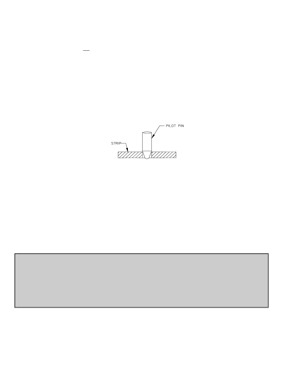
8. Jog the press down slowly observing when the longest pilot would engage the pilot hole in the material if the material
were there. (Refer to Figure 4.) Note the press positional readout and put this setting into your Programmable Limit
Switch (PLS) for the ‘Pilot Release On’ setting. The ‘Pilot Release Off’ setting, in most cases, should be 180º.
(See Figure 5.) Some drawing applications require the rolls to remain open past 180º.
FIGURE 4
9. Continue to jog the press slowly until the longest pilot just comes out of the material. Note the press positional
readout and put this setting into your PLS for the ‘Feed Cam On’ setting. Set the ‘Feed Cam Off’ point so that
there is enough time to complete the feed length and enough time to stop the press, if there is a feed fault. (See
Figure 5.)
10. Set the ‘Reset Cam On’ for 180 degrees and ‘Reset Cam Off’ for 200 degrees. This setting should never need
changing. (See Figure 5.)
1.5 THREADING THE TOOL
For a comprehensive description, refer to the Ultra Magnum Servo Roll Feed Operation Manual.
NOTE ABOUT CAMS:
The Feed Cam (open tool): The feed system uses this press cam for timing the feeder to the press crankshaft.
Although no shafting or belts actually connect the press to the feeder, the feed must be “told” when it is safe to move
the strip and when the feed move must be completed.
•
This “connection” is an electrical one, and not a mechanical one. This gives the Operator/set-up personnel total
flexibility in deciding when the feed progression should take place.
•
Each die set can have a unique ‘Feed Angle’. This ‘Feed Angle’ is dependent upon many variables; pilot and
punch length, press stroke, strip forming in the die, etc.
Put the Ultra Magnum control into “JTL” mode. All the adjustments to the feed system and press have now been
made. The press is at Top Dead Center (TDC) and ready for automatic cycling. Proceed by advancing the material
using Jog Forward button on the jog pendant until WAITING FOR PRESS is seen in the display and inch the