Introduction, Warning – MoTeC DBW-4 User Manual
Page 3
MoTeC DBW-4
3
Introduction
Introduction
This manual describes the functions and specifications of the MoTeC DBW4, and configuration for use with the
MoTeC “hundred” series ECUs (M400, M600 & M800). The DBW-4 works with ECU Firmware V3.30T and later.
The DBW4 provides 4 PID Controllers for drive by wire control or generic PID control.
PID Set points are received from the ECU over the CAN bus and are separate for each PID Controller. Each
controller can be individually configured for use as a generic PID Controller or drive by wire PID Controller.
When configured as a drive by wire PID Controller, the throttle position is tracked with 2 analog inputs for each
throttle body. Error checking is done on these inputs to ensure safety. Drive by wire PID Controllers have some
common functionality in that if one controller must be shutdown, for safety or due to an error condition, all other drive
by wire PID Controllers will be shutdown automatically.
When configured as generic PID Controllers, only one analog input is used per PID Controller for feedback, leaving
the remaining analog input for general use.
All scaled analog input values are transmitted over the CAN bus as well as PID fault conditions.
The DBW-4 has the following inputs and outputs:
•
8 Analog voltage inputs (AV 1-8) for PID Controller feedback and generic use.
•
8 PWM outputs (4 pairs) for PID Controller output.
The DBW-4 uses a 66 pin Autosport connector.
WARNING!
Drive by wire throttle body motors are very powerful and can cause serious injury to users or damage to the
throttle body. Never attempt to move the butterfly by hand with the motor connected to the DBW-4 Unit.
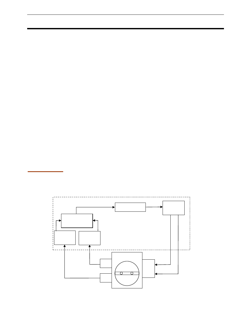
Figure 1: DBW-4 Unit in a drive by wire application
O
u
tp
u
t
B
Measured Value
O
u
tp
u
t
A
PWM2
PWM1
PID Controller
Measured
Value
1
Measured
Value
2
TP2
Throttle Body
Measured
Value Tracking
PWM
Output
TP1
Motor
DBW-4 Unit