MoTeC DBW-4 User Manual
Page 12
MoTeC DBW-4
12
Introduction
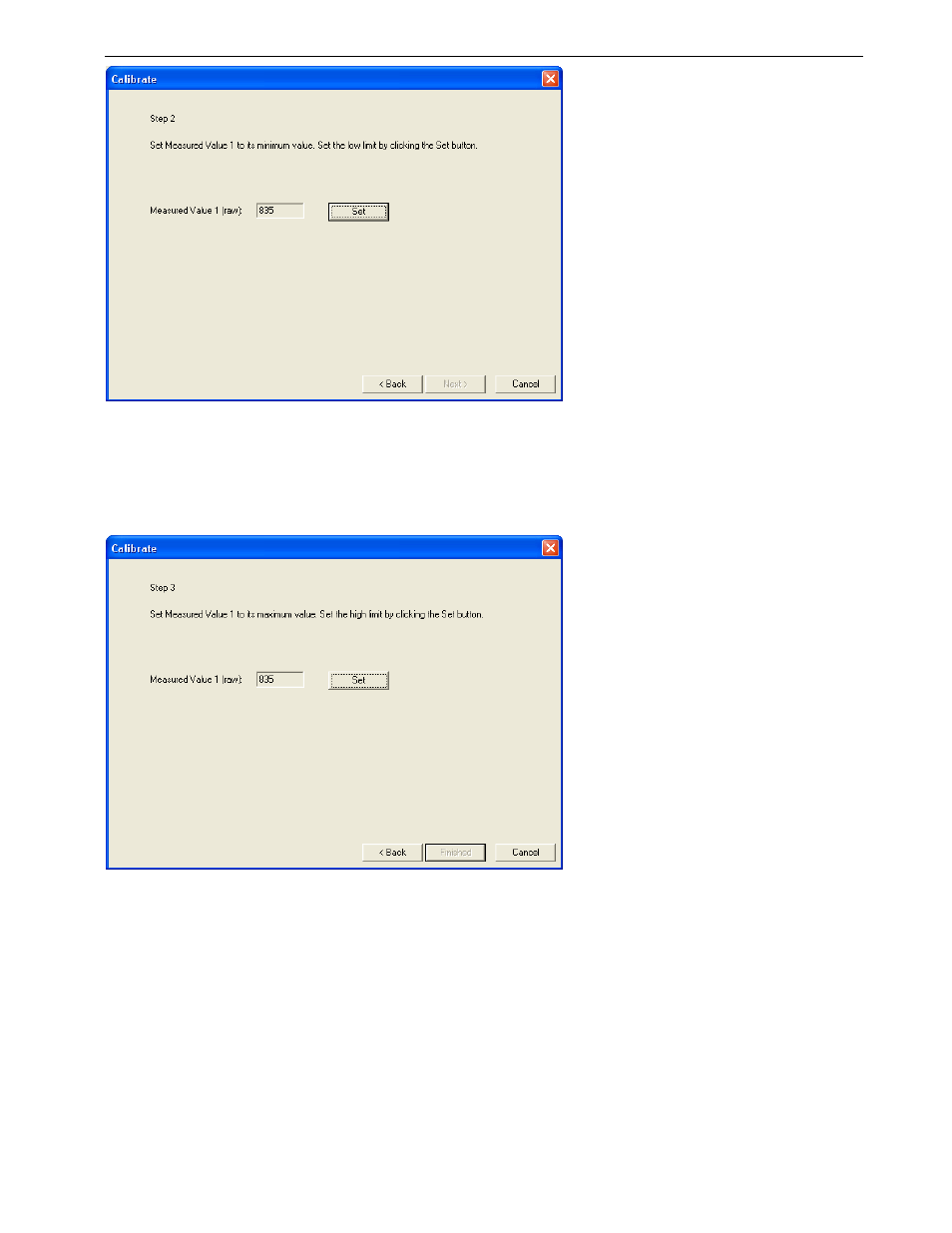
Step 5:
Set the high limit for the measured position by following the instructions displayed (see below). For indication
purposes, the raw position value will be displayed as the actuator position is changed. Note that the Set button can
be pressed again if the measured position was set incorrectly. When the high limit position has been set, click
Finished to continue.
Step 6:
When all calibrations have been performed, send the configuration to the DBW-4 by pressing the F5 key.
See also other documents in the category MoTeC Hardware:
- ADR (25 pages)
- ACL VIM (99 pages)
- ADL EDL (81 pages)
- ADL2 EDL2 (82 pages)
- ADL3 EDL3 (80 pages)
- AFM1 (20 pages)
- BR2 BTX (47 pages)
- BRX (21 pages)
- C125 (89 pages)
- C185 (85 pages)
- CDL3 (86 pages)
- Display Creator (66 pages)
- E888 (30 pages)
- GPS-BL1 (8 pages)
- GPS-G1 (7 pages)
- GPS-L5 (8 pages)
- Interpreter (37 pages)
- Knock SKM (36 pages)
- LTC (39 pages)
- M1 Series Quick Start Guide (1 page)
- M1 Tune User Manual (77 pages)
- M4 (63 pages)
- M400 (101 pages)
- M84 (86 pages)
- MDC (22 pages)
- MDC2 (20 pages)
- MDD (48 pages)
- PDM16 (61 pages)
- PLM (59 pages)
- PWC Plug-In ECU (91 pages)
- Screwdriver ECU (5 pages)
- SDC3 (24 pages)
- SDL (70 pages)
- SDL3 (76 pages)
- Snowmobile Plug-In ECU (46 pages)
- VCS (36 pages)