Appendix e: dbw-4 to m800 wiring, Motec dbw-4 18 introduction, Dbw-4 power and ground wiring – MoTeC DBW-4 User Manual
Page 18
MoTeC DBW-4
18
Introduction
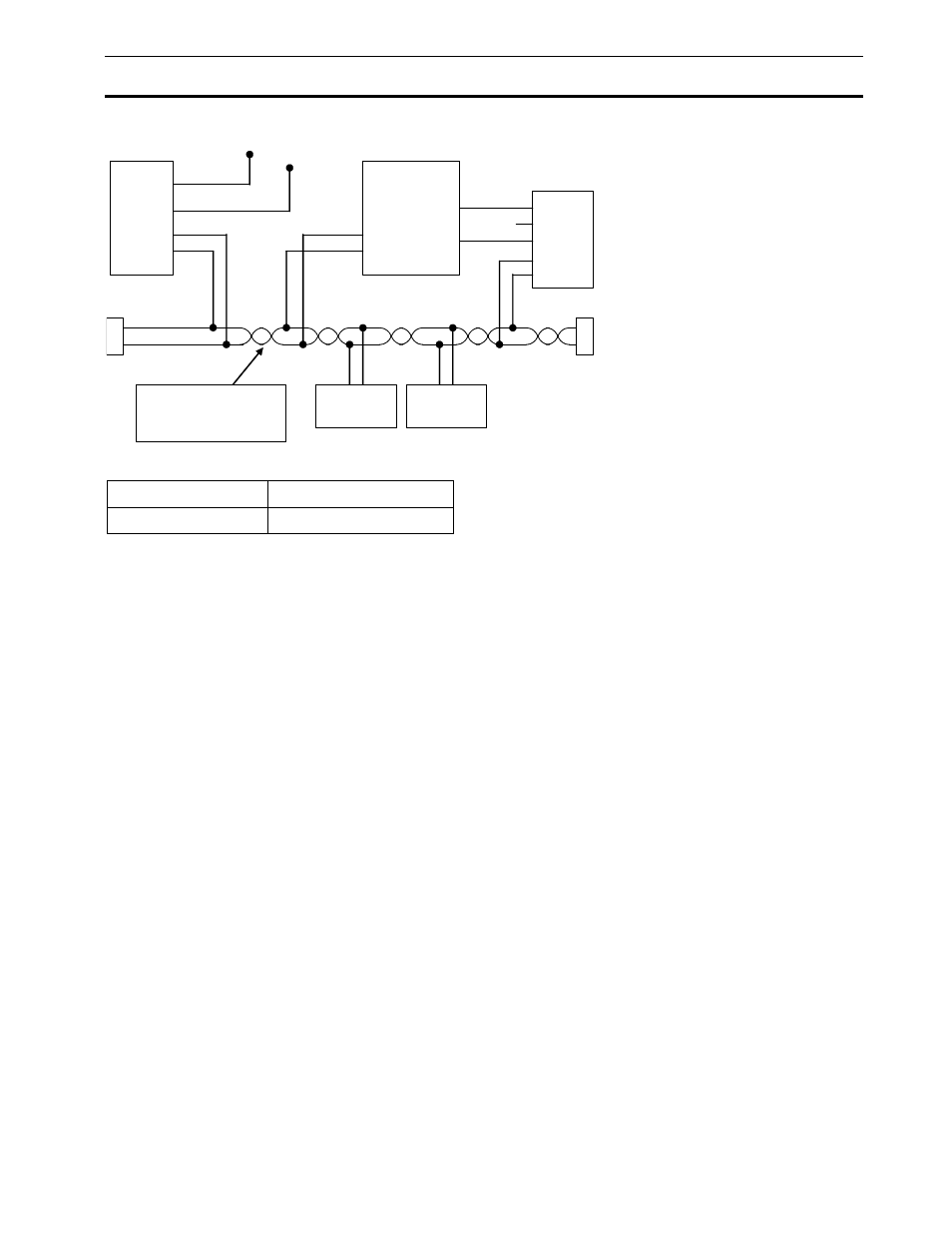
Appendix E: DBW-4 to M800 Wiring
See pin list
Ground
DBW-4
ECU
See pin list
Power
47
CAN-LO
CAN-LO
B24 / 47
54
CAN-HI
CAN-HI
B23 / 48
CAN-LO
CAN-HI
Any Other
CAN Device
1
0
0
R
1
0
0
R
See the CAN Bus
Wiring Specification
for more Detail
CAN Cable
Connector
Any Other
CAN Device
0V
1
8V
3
CAN-LO
4
CAN-HI
5
2
0V
8V
72
71
Bat -
Bat +
DBW-4 Power and Ground Wiring
Bat +
Bat -
28, 29, 30, 37, 38, 39
13, 14, 15, 19, 20, 21, 22
Additional Power and Ground pins are provided to simplify and to meet the current requirements of any devices
connected to the PWM outputs.
As a general principle, if no outputs are being used, then wiring one power and one ground pin is sufficient. If the
DBW-4 outputs are used, then all power and ground pins should be wired up.
Wire to suit connector : 22# Tefzel, Mil Spec : M22759/16-22