Index drive oil capacities (approximate), Oil seal installation recommendations – DE-STA-CO INDEX DRIVES GENERAL SERVICE MANUAL User Manual
Page 7
6
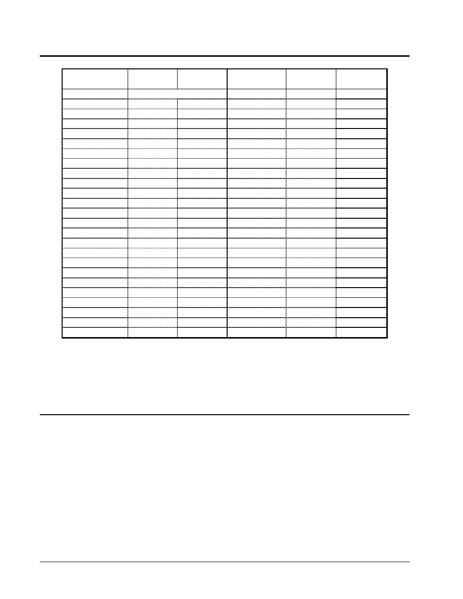
Index Drive Oil Capacities (Approximate)
For indexers mounted in the normal* position. Consult IMC for units not listed.
Model No.
US.
Metric
Model No.
U.S.
Metric
(quarts)
(liters)
(quarts)
(liters)
80RDM
Grease filled**
40RGD/S
6 oz.
0.2
601RDM
2
2
50RGD/S
16 oz.
0.5
902RDM
3
3
70RGD/S
20-24 oz.
0.6-0.7
1100RDM
8
8
80RGD/S
30-38 oz.
1-1.1
1305RDM
9
9
110RGD/S
C/F
C/F
1800RDM
36
34
350RGD/S
1
1.4
425RD
2
2
500RGD/S
5
4.7
800RD
5
5
700RGD/S
10
9.5
1301RD
14
13
1801RD
36
34
1100RNG
C/F
C/F
1550RNG
C/F
C/F
250P
1
1
2050RNG
C/F
C/F
387P
2
2
512P
5
5
750E
C/F
C/F
662P
10
10
950E
10 gallons
38
900P
20
19
1150E
25 gallons
95
1200P
48
45
1550E
40 gallons
152
1800P
95
90
2050E
45 gallons
171
2750E
75 gallons
285
401RA (C)
1
1
512RA(CC)
2
2
150RPP
2.5
2.4
662RA(CCM)
6
6
300RPP
4
4
663RAD(DR)
4
4
500RPP
10
9
900RAD(GH)
6
6
900RPP
48
45
* Normal indexer mounting position is output vertical over input on all models except the "Parallel series" (P)
in which normal mounting is output horizontal, even with input. “Output Vertical” refers to the direction of the
center of rotation. For dial-type indexers, this is the position with the dial horizontal.
** “Grease-filled” units are shipped with grease. Grease should only need to be added if the unit is
disassembled for rebuild or repair.
C/F: Consult IMC for information
Oil Seal Installation Recommendations
IMC recommends that all seals be replaced any time the device is being disassembled regardless
of whether they are damaged or not. Most damage to oil seals occurs at assembly when
recommended seal installation procedures are not followed.
1. Check dimensions -- to be sure that shaft and bore diameters match those specified for the seal
selected.
2. Check seal -- for damage that may have occurred prior to installation. A sealing lip that is turned
back, cut or otherwise damaged should be replaced.
3. Check bore -- to see that the leading edge is deburred. A rounded corner of chamfer should be
provided.