P.24, 7 typical performance diagrams – Camco D-Power 1 User Manual
Page 25
D - P O W E R
S E R I E S
USER MANUAL
D-POWER 05/1
P.24
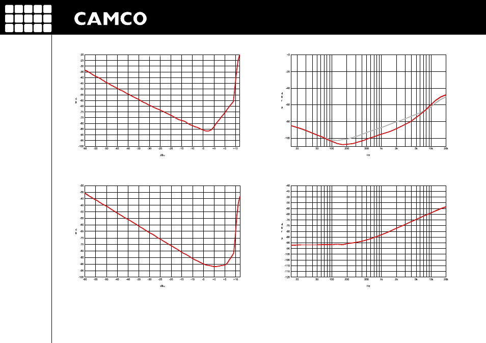
Figure 7.6
DIM 100 intermodulation distortion @ 8 Ω vs. input level
(Measurement of a typical performance of D-POWER 1)
Figure 7.8
Common mode rejection ratio
(Measurement of a typical performance)
Figure 7.5
SMPTE 4:1, 60 Hz, 7 kHz vs. input level
(Measurement of a typical performance of D-POWER 1)
Figure 7.7
Channel separation vs. frequency @ 50 W / 8 Ω (channel 1,
channel 2
)
(Measurement of a typical performance)
7 TYPICAL PERFORMANCE DIAGRAMS
This manual is related to the following products: