Autel Maxivideo MV201 User Manual
Page 6
Description, Specification and Tool Components
Tool Components
5
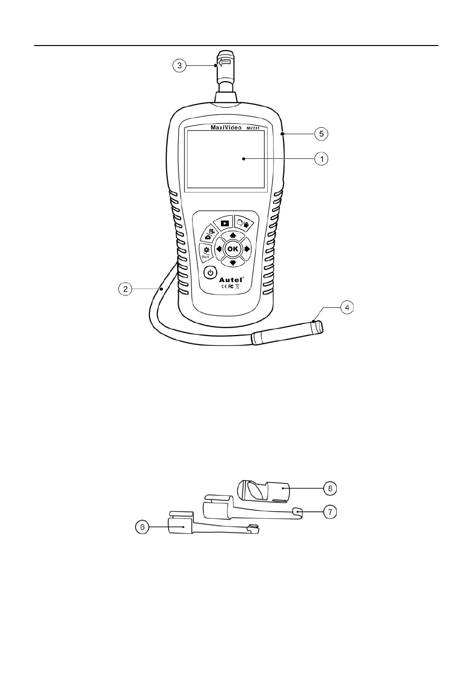
Fig. 1
1) LCD Screen – Indicates still images and videos.
2) Cable – Connects to the tool while in use.
3) Cable Connector – Connects the display unit to the imager head
and cable.
4)
1
Imager Head – Connects to the cable to view real-time images.
5) Rubber Boot – Protects the tool from drop, abrasion, etc.
Fig. 2
6) Accessory Magnet – Picks up small metal objects such as
dropped rings or screws on the floor.
7) Accessory Hook – Unclogs obstacles and picks up wires in the
pipes or confined areas.
8) Accessory Mirror – Helps users look around corners and see