2 setting 3-/4- wire system 4 – 20 ma, /4-wire system 23, Test run – AUMA Electric part-turn actuators SG 05.1 - 12.1_SGR 05.1 - 12.1 NORM User Manual
Page 23
17.2 Setting 3-/4- wire system 4 – 20 mA
.
Connect voltage to electronic position transmitter.
.
Move valve to end position CLOSED.
.
Pull off indicator disc.
.
Connect ammeter for 0 – 20 mA to measuring points (figure P-3).
The circuit (external load) must be connected (observe max.
load R
B
), or the appropriate connections at the terminals
(refer to wiring diagram) must be jumpered, otherwise no
value can be measured.
.
Turn potentiometer (E2) counterclockwise until stop is felt.
.
Turn potentiometer (E2) slightly back.
.
Turn potentiometer “0” clockwise until output current starts to increase.
.
Turn back potentiometer “0” until a residual current of approx. 0.1 mA is
reached.
.
Move valve to end position OPEN.
.
Set potentiometer “max.” to end value 16 mA.
.
Move valve to end position CLOSED.
.
Set potentiometer “0” from 0.1 mA to initial value 4 mA.
This results in a simultaneous shift of the end value by 4 mA, so that the
range is now 4 – 20 mA.
.
Approach both end positions again and check setting. If necessary, correct
the setting.
If the maximum value cannot be reached, the selection of the
reduction gearing must be checked.
23
Part-turn actuators SG 05.1 – SG 12.1 / SGR 05.1 – SGR 12.1
Operation instructions
AUMA NORM
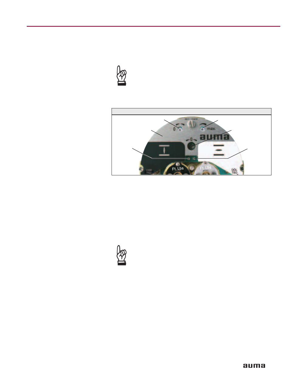
Figure P-3
“0” (0/4 mA)
“max.” (20 mA)
Meas. point (+)
0/4 – 20 mA
Meas. point (–)
0/4 – 20 mA
Cover plate
E2